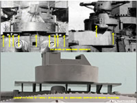
Box art for the Takom kit
Background
Takom is a model producer based in China. Although they specialise primarily in armour (tank) kits, they have branched out into other areas such as ships and aircraft. One of their more unique and interesting product lines, however, has been a series of warship turrets in 1/72 and 1/35 scale. Among these are included turrets from Yamato, Missouri, Bismarck, Scharnhorst and now Hood.
Kit Contents & Moulding/Detail
Contents - This kit consists of @153 injection/slide moulded pieces in grey plastic. There is a single piece base, two barbette halves, two turret/gun house pieces (main body and bottom) plus four sprues/trees. There is also an 11 page instruction booklet complete with colour images depicting the turret in 1940-1941 and 1937-1938. Unlike previous offerings, there is no photoetch included in this kit. Although the box art shows the turret as of 1940-41, one can actually build and paint the turret as it would have appeared from the early 1930s onward.
Moulding - is very crisp overall with virtually no flash. There are a few shallow pin "dimples" and light raised lines here and there from the moulding process, but these are easily removed where necessary (but be advised that some are meant to depict borders between flush parts). There was no warping, broken or missing parts in my example.
Construction
The instructions are largely east to follow and construction is straightforward. If built straight from the box with no modifications, this is a very quick and easy build requiring minimal tools and experience. If one desires accuracy, be prepared to devote much more time to the kit.
Accuracy & Final Assessment
This kit is a "mixed bag." On one hand, its certainly a "cool" idea for a kit in that its appealing and unique and fairly inexpensive. On the other hand, it does come across as somewhat toy-like and it suffers from numerous accuracy issues. They may have misunderstood and/or used incomplete/lacking research materials. Despite the errors, it does look enough like Hood's "B" turret to satisfy many modellers who don't care about total accuracy. Modellers who want excellence (and something more than a toy) however, may wish to think things over before getting this model. Consider how far you are willing to go and how much time/effort you want to expend. To help you with this determination, we've provided some detailed "Corrections & Suggestions for Improvement" below.
Corrections & Suggestions for Improvement
Next, we'll cover the various subsections of the model starting at the bottom and then working our way up. Please note that we've provided numerous photos as well. Simply click on a photo to open an enlarged version.
 Base
Base
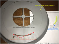
The circular base is 8.6" / 22cm wide and features nicely bevelled edges. Our example was flat and free of any warping. It lends itself well to just about any stylistic approach (i.e., wood grain effects, solid colour, etc.). It does suffer from some detailing issues though.
Planking- The planking is crisply moulded but a little narrow for scale (the kit planks scale to @7"/0.18m but the actual ship had 9"/0.23m wide planks). Unfortunately, the planking pattern is incorrect, or rather, incomplete: All plank lines end @3/16" / 5mm from the edge of the barbette, resulting in a blank/flat circle on the deck. Hood's planking actually reached the front and rear faces of the barbette. On the port and starboard side of the actual barbette were border/edge planks called cutting pieces. These were curved on the inner sides and notched/angled on the outer sides. Using a source such as the excellent "Anatomy of the Ship" book by John Roberts, modellers should be able to draw and/or scribe the missing features. Of course, one could also opt to rebuild the planks with strip styrene or perhaps even paint the extra detail in.
 Breakwaters - The kit features a small portion of the ship's "B" turret breakwaters (parts C2 and C3). Takom erroneously have you glue part(s) A4 to the front of each breakwater. Presumably A4 is meant to represent the stowed "door" of the breakwater (which, in real life, could be removed and physically stowed on the front of the breakwater...but NOT in the position this model indicates. The shape was also a bit different). We recommend skipping this and filling/sanding the mounting holes instead.
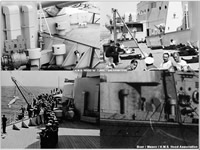
Additionally, the rear supports (parts B8) are very "basic" and not tall enough (the actual supports reached nearly to the top of the breakwater - see the photo to the right). These should be fairly easy to replace with styrene stock if you're so inclined. If you opt to use the kit parts, these could easily be enhanced with plastic stock (add a flat piece on the rear edge). One could also add the small bar struts that were in this area on the actual ship. You can see these details in the photos to the right.
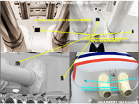
 Barbette & Vents
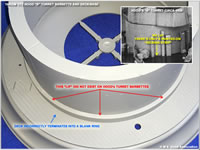
Barbette - In terms of size, the assembled barbette structure is acceptably close (its scales up to about 1ft/0.3m taller/wider than the real thing). Unfortunately, this same structure also incorporates the kit's biggest/most significant error: Takom have included a @9mm tall 'lip" which protrudes round the bottom edge of the barbette where it meets the deck. Hood did NOT have such a lip around any of her four main turrets! The only feature in this area (during peacetime) would have been a painted-on stripe at deck level called a "kicking strip." Needless to say, removal of this "lip" and correction of the barbette sides would be MAJOR surgery. Its further complicated by the need to fill the two large mounting slots in the deck/base (not to mention the additional blank deck space that would be exposed).
 Mushroom Vents - There were several "mushroom" style vents of various sizes (ranging from 7.5" to 20.5" in diameter) which were positioned immediately around Hood's "B" turret. Unfortunately, Takom includes only two of these (one small, one large), both of which are on the starboard side only. The larger one is a tad small for this scale and its shape is too squared-edged . The smaller vent is significantly too small and incorrectly shaped. It should be easy to reshape the large vent and alter or recreate the other vents using plastic stock, wood dowels, brass, etc.
We're surprised that Takom failed to include the other mushroom vents, especially the large 20.5" diameter mushroom vent positioned on the port/forward side of the barbette. Prior to 1940, this vent was the same height as the large kit-provided vent to starboard. Sometime that year it was significantly elevated in height. As a result, this vent was particularly prominent. As stated previously, it should be fairly easy to replicate the missing vents if one wishes to.
 Upright Rectangular Vents - These are generally well-moulded, though their mounting brackets are very thick for this scale. This is a minor issue though. Some of the panel detail present on the actual vents is missing, which again is minor considering the scale. One can add these with very thing styrene sheet, or omit them altogether.
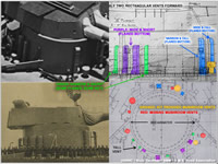
The most serious issue with the vents is that Takom has too many, some are wrong style/size and some are not in the correct positions. In reality, the vents around Hood's "B" barbette varied in appearance: some had straight sides/bottoms and some had bottoms which /flared out shortly above the deck. Additionally, some vents were narrow/slim and others were wide. There were also differences in height (all but three were more or less the same height with the three exceptions being particularly taller than the rest). As for position, Takom got it close but the positioning on the aft side is slightly off (though close enough for most folks to ignore). The image to the right shows the correct positions of the vents. It also depicts the width and style (straight sides or flared bottoms). It may be possible, by swapping out some of the vents and slightly altering their positions to make the kit better match the real ship. One can also potentially enhance the vents by thinning-down the mounting brackets and adding panel details.
Other - There is much missing detail around the barbette. As previously noted, there should be more mushroom vents. There should also be a pair of small bollards, pipes (passing through the breakwaters), and likely a vertical ladder (it was originally mounted on the inboard side of the front/centreline rectangular vent, but appears to have been moved later, possibly to the rear of the barbette (though this is not 100% verified and remains conjecture). One could possibly also include winches.
Turret/Gun House Assembly
 The overall size and shape of the turret/gun house seems correct, but there are various incorrect, missing or incomplete details which are covered in more detail below.
- Barrels & Blast Bags -The barrels are nicely moulded though lacking some "ring" detail at the muzzle. This can be overlooked if one uses the kit-provided tampions (though these are very plain and lack the chough & anchor badge). The blast bags are excellent and come in two variants, level and raised (one could also combine the two). Note: if you build the turret pre-war, please note that there were shiny silver-coloured bands strapped around each barrel near the muzzle. The muzzle end of the guns forward of the bands were unpainted metal. If modelling the ship in wartime, the kit barrels are fine as-is (don't add any bands plus be sure to paint the entire barrel). Also, remember that the blast bag colour was only white during the pre-war years. If building wartime Hood, the blast bags would be the same dark Home Fleet Grey as the turret and guns!
 Lower Rear Turret/Gun House Dropped "Deck" missing- All four of Hood's actual turrets/gun houses featured a section at the lower rear which hung down/protruded below the lip of the barbette. The kit does not feature this lower section. One could easily replicate the feature using sheet styrene.
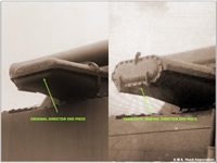
- Vents on Turret/Gun House Rear - The kit includes twin vents (parts A14) but they are incomplete because they attach to the rear bulkhead of the turret only. In reality, Hood's "B" turret vents ran down the turret's rear bulkhead and then curved UNDER the rear of the turret. They extended forward roughly halfway to the barbette. This was the same on both "B" and "X" turrets. Takom overlooked this lower portion (as well as a hatch in the lower deck). This is easily remedied by building the lower sections using styrene strips.
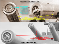
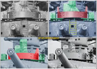
 Ladder and "Windows" on Turret/Gun House Face - The three view ports in the front of the turret are nicely represented. Takom calls for parts D10, D14 & D15 to be glued inside of these openings. These parts are all incorrectly shaped and excessively thick. Takom also have them mounted too far forward in the "windows" (making them VERY noticeable). Hood did indeed have optical devices in these openings: single ones in the outer openings and what appears to be a dual/binocular device in the centre window. All were much less prominent and set farther back. We recommend omitting these parts entirely or perhaps replacing them with something slimmer...and set farther back. As for the ladder (part D9), its not shaped exactly the same as the real ladder (the ends mounted to the turret differently), but its close enough to work.
- Missing Features Atop Turret/Gun House Roof - The bolt heads and roof armour plates are crisply moulded and mostly correct, but there are five bolt heads missing. There are also a pair of stanchions missing. Additionally, the kit's roof armour plates sit slightly proud of the turret edges. This results in a step around the top edge near the bolt heads. In reality, the armour plates were flush with the sides of the turret. This could possibly be filled and sanded, but it will be tricky work requiring great care due to the proximity of the bolt heads.
The kit is missing an open director foresight. This was located on the real "B" turret turret/gun house roof just forward of the director "wing." The structure was just to starboard of the centreline and positioned just in front of the large/prominent open direction sight (which is composed of parts C13, 14 and 16). This can easily be replicated with a thick piece of styrene that is rounded on the top and left/right ends.
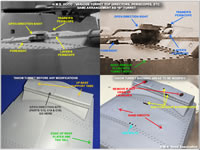 Turret/Gun House Director - The large "wing-like" structure at the top/rear edge of the turrets housed a telescopic director. This allowed the guns to be aimed locally from the turret/gun house in the event that the main gunnery directors atop the bridge were not available. The overall dimensions appear to be close, but the general shape is a bit too "squared off." The front and rear edges of the uppermost portion of the kit's director are too vertical (these were more sloped with rounded edges aboard the real ship). This general "squareness" also affects other director parts (most notably the main pieces from page 6's step 5).
- Main Director (Crescent) Hood - This consists of parts C13,14 and 16. The lower piece (C14) is notably thicker and slightly taller than it should be. The crescent shield (C13) is also too thick. It should sit slightly higher than it does on the model. It also lacks prominent attachments on its rear surface (the actual sight hood/windscreen was attached with longer pieces of metal). Despite these issues, it looks enough like the real thing for most people to use the parts as-is.
 Missing View port/Periscope on Director - There is another missing window-like feature to port of the aforementioned sight direction hood. It had rounded upper corners on the actual ship. Once can easily replicate this with appropriately shaped sheet styrene or a raised layer of paint. One could also attempt to depict it as open by cutting it out. Lastly, all four main turrets had a periscope located on the top of the director "wing" just to port of the aforementioned crescent hood. This can easily be replicated with round strip stock. These are very easy additions.
- End Cap Details - The centre sections of the director end pieces (parts C17 and 18) are slightly off in appearance. Namely, the overall shape is too squared. It should have more rounded fore/aft corners. The same shape problem affects the protruding rectangle in the centre of these pieces. These should be more rounded on each end. This may be very difficult to correct. Additionally, there are details missing from theses pieces. First, there are not enough bolts. Second, the pieces are missing a small curved piece at top centre and two hinge/connector features near the bottom edge corners. These could likely be added with styrene strip.
UP Rocket Launchers- The construction of the UP assembly is covered in Steps 7 through 10. There are several significant errors.
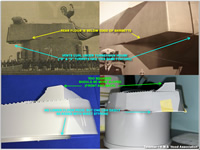
 UP Platform Shaped Wrong - Takom erroneously depicts this as one large rectangular platform (part C4) supporting a circular central platform (part C1) and a pair of ammo boxes. In reality, there was no single large platform. It was actually composed of three platform structures: there were an outer pair of small rectangular platforms (one to port, one to starboard) and a centre circular platform (with only a little overlap at the front outer edges of the circle). Each outer platform was half as deep as part C4 and supported one ready use ammo box while offering a very small working space to stand. The circular area formed the rest of the platform/deck and supported the actual UP projector.
In order to correct this, one would have to cut C4 into multiple pieces or replace it entirely with sheet styrene. This will also affect the underside supports (more on these below) and of course, the amount of railing used.
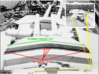
 Circular Splinter Shield/Bulwark Wrong- Takom failed to add the raised sections of the circular splinter shield/bulwark which surrounded the launcher (part C1). The real structure was not one uniform height, but actually doubled in height for short spans directly to port and to starboard. Simply add sheet styrene to the applicable locations on part C1. In the photo to the right, the main UP platform, launcher and ammunition boxes are shown in green. The splinter shield/bulwark is red. Another view can be seen by clicking here.
- Underside Supports Wrong - There appear to be the correct number of underside supports, but the shapes and positions are either questionable or outright wrong. The most notable problem areas are the outermost supports and the two large rear supports. On the real ship's UP platform, there were supports under the outer and inner edges of the two ready use ammo platforms and under the outer edges of the circular platform. There appears to have been at least one support under the front of the circular platform (offset to port so as not to interfere with the various periscopes and open site director).
At the rear, things are less clear. We see indications of at least one large strut connecting (at an angle), the rear of the turret to the rear of the circular platform. There is little photographic evidence of anything else in this area. Its hard to tell if there was anything supporting the central underside area of the circular platform below or near the position of the UP projector itself. Its probably a moot point for this model since that area is all but impossible to see once assembled. At any rate, if one chooses to correct part C4, it should be fairly easy to build correct underside supports using styrene stock.
- Missing Mesh Cover - Real UP launchers (at least those aboard Hood) had a metal mesh covering which surrounded the rocket tubes (at least the top and sides). This could easily have been provided using photoetch. This is a great candidate for future aftermarket offerings.
- Rails - These are adequate though a bit thick for this scale. As mentioned previously, you'll need to use less railing if you reduce and reshape part C4. The rails are decent, but they could have benefited from photoetch. Once could potentially replace or augment them by using plastic or metal stanchions and very small chain or photoetch chain.
 Considerations for Earlier Versions of B Turret - Of course, if one is building a pre-1940 Hood, simply omit the whole UP assembly and apply the applicable paint colours. We do recommend that you cut/sand the mounting tabs off the top of the director though. Its also advisable to consider adding the periscopes/details mentioned previously. Otherwise, its very 'bare" looking in that area. By doing this, you can build the turret as it appeared from the early 1930s onward using the kit-provided parts.
If you wish to build an earlier (1920s) version of Hood, it will require some additional work, specifically to the director ends. This is because Hood's turret rangefinders were originally configured slightly differently. As originally built, there were no hinged end caps and the ends had the same "lip" with bolts as the front and rear of the director. It might be possible to replicate the original look using the existing pieces and strip stock. The main difficulty would be in creating accurate bolt heads. This may be another candidate for aftermarket parts. Additionally, one would have to build the aircraft flying-off platforms carried by Hood in the 1920s and early 1930s.
Painting Instructions
The instructions depict two paint schemes. The first is "as sunk" in May 1941. The second is from 1937-38 during Hood's time in the Mediterranean. Of course, there are more options one could choose depending on the timeframe the kit is being built to depict. For specifics, please consult our article on the Paint Schemes of H.M.S. Hood, 1920-1941
Aftermarket Parts
At the time of writing/initial posting there is only one aftermarket set for this model, the Chuanyu Model Ship set containing a wooden deck veneer, metal gun barrels and scale 15" projectiles. This set is not recommended as its poorly researched and executed. The deck is completely incorrect in that the planks are half they size they should be and the cutting edge and border piece details are missing. The guns are okay, though our copy showed tooling marks. Overall, it appears to have been rushed into production with no effort being taken to make it actually more accurate than the kit. Don't waste your time or money on this one.
Hopefully other manufacturers will see this kit and realise the opportunities this model presents. It would be nice to see things such as 3D printed guns, tampions, turret top details, corrected director end caps, corrected upright vents, mushroom vents, etc. It might be nice to also have 1920s style director ends and aircraft flying off platforms. If any manufacturers are interested in pursuing this, we'd be happy to help provide information.
Photos of Completed Kit (Coming Soon)
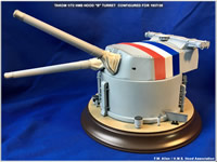
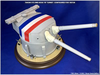
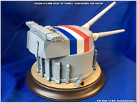
Shown here are examples of completed Takom 1/72 H.M.S. Hood "B" turret models.
 |
 |
 |
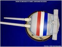 |
| Above - Assorted views of the Takom 1/72 Hood turret built by FW Allen. This model was updated (somewhat) using this article and represents the turret as it appeared in 1937/28. Click to enlarge. | |||