START OF TRANSCRIPTION
MOST SECRET
INTERFERENCE PHENOMENA IN TYPE 279 R D/F
TO THE COMMANDING OFFICER, H.M.S. HOOD
FROM R D/F OFFICER.
April 14, 1941
1. On several occasions in the Atlantic unexplained interference phenomena have been observed on the screen of Hood's type 279 R D/F. At 1010 on April 9th the phenomena were sufficiently clear and well defined to enable tests to be carried out, as a result of which the following characteristics were discovered:
(i) The phenomena appear all round the elliptical scan as "grass" running up to saturation and effectively blocking any echoes.
(ii) They are no connected with the transmitter or with the alternators: they were observed to continue when the transmitter was closed down and when using either alternator.
(iii) They appear on all scans and with both P.11 and P.12 receivers, but disappear when the aerial is disconnected, thus establishing that the interference is picked up by the aerial.
(iv) On the C.R.T. the "grass" appears at times to separate into several distinct groups which move round the trace, suggesting that the phenomena are a series of pulses repeated fairly rapidly, the estimated repetition frequency being between 1,200 and 1,700 c/secs. The pulses would appear in fixed positions on the elliptical scan when the repetition frequency was an exact multiple of the set's repetition frequency. The variation of the 279M repetition frequency gives the continuous movement of the pulse round the scan, and when this becomes rapid the "grass" of the pulse appears continuously.
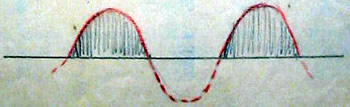
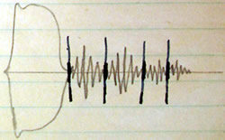
(v) The appearance on the C.R.T. long scan is as shown below:
——page break——
- 2 -
The length of the pulse and the distance between the pulses appear to be equal and as the envelope (shown in red) has a half sine-wave shape it is possible that the transmission is actually a continuous wave of frequency between 1,200 c/sec and 1,700 c/sec, the negative half (shown dotted) being rectified by the receiver.
(vi) The "grass", or "noise", when seen on the RB unit L 10 (fast scan) appears as a definite oscillation like this:-
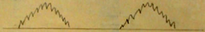
The frequency of this oscillation was obtained by finding the wavelength on the ranging unit. This was about 700 yards, which gives an approximate frequency of 500 kc.
(vii) The phenomena were very sharply tuned on all stages of the receivers and the radio frequency was 40.5 megacycles. H.M.S. Kenya, in company, did not pick up the interference when working on 41 megacycles.
2. From these observations it would seem that the interference has two definite frequencies (a) 40.5 mcs and (b) approximately 500 kcs. It is either a pulse, such as a spark transmission repeated at a frequency of 1,200 to 1,700 c/sec, or a continuous transmission with this low frequency in addition to (a) and (b). It could not be traced to any local source of interference such [as] W/T or DG.
3. On April 14th trials were carried out with Cossack's Asdic to determine if this caused the interference, but no signs of it were observed.
4. Positions at which the phenomena were observed are below:
Date |
Appeared |
Disappeared |
Position |
| April 9th |
|
|
50 50 N 19 40 W |
| April 9th |
|
|
49 08 N 20 33 W |
| April 13th |
|
|
50 49 N 19 08 W |
5. All these tests were carried out under the direction of Mr H.J.W. Reeves, of H.M. Signal School, who was on board at the time.
——page break——
-Routing Sheet-
Report on the Installation, Performance and Trials of 279M in H.M.S. Hood
30/4/41
1. Many interesting points are here described. In general it seems that our first 279M ultimately worked very well.
2. [first two words illegible] will note important matters to be included in the 279M spec.
III
The report has much of interest, the writer was present during the fitting of the set and many points mentioned were discussed at the time. It might assist to comment upon some aspects of the report.
Para 2. The author is optimistic in suggesting even by inference that it is easier to run pyrotenax than open feeders, it is however a more satisfactory job.
Para 2.4. Can a suggestion be advanced as to how an internal number of 1/2 can be evaluated where it is difficult to measure the distance between offices accurately?
Para 2.5 Hood's stores position was not only bad, in the opinion of the writer who was the Fitting Out officer it was disgraceful. Some items required for first fitting were never received, other items notably a great amount of the main rectifier and mast for C.R.T. unit we had to persuade S.E.E. and/or ship's staff to fabricate. We could not make oiler valves and had to send off an officer to collect 2 valves in order that the main oscillator could be got going. Repeated signals from the ship sent by Flag Lt Cdr to S.N.S.0 and C.S.S. were not even acknowledged. It was at one time necessary for the A/S to personally chase stores.
Para 3. With capacitative coupling is there a direct D.C. path for lightning surges?
Para 3.2. Suggest a paragraph be added to handbook giving this information.
Para 3.6. This automatic B.T.U. and the obvious disadvantages mentioned here been discussed with B.H. and Lt Cdr Hartly. Suggest application officers may have further comments.
Para 3.7. This is important and it is essential that basis of power calculation be made clear to operators if M/A is fitted to transmitter panels. This latter measure has been advocated in a minute by the writer circulated under M1714/41.
Para 4.3. This information should be circulated as speedily as possible and necessary instructions passed to E1 to ensure that correct grade of seekay wax is supplied.
Para 4.6. An old trouble found in the maker's m/c's, it is gradually being eliminated.
Para 4.7. Concur with above [illegible] R.1. 13/6
[Signature] Pritchard
——page break——
CONTINUATION SHEET
This is an excellent report, but I wish it had included a summary in the recognised manner. I have had to read all through it to make sure I didn't miss anything important and it has taken me nearly half an hour.
B6. Would you let me know sometime what is on going about the bearing transmission difficulty.
[initials] CS Cdr 21/6
I don't understand the marking of the paper. It is marked to R3 for a 2nd time for no apparent reason, it is not marked to E1, though Pritchard wants it circulated to him speedily. Would you then amend circ. as you think fit. [initials] CS
Cdr A. Para 3.6 & 6.7 re R.I.S. [initials CS]
It has been clear for sometime that power supply alternators with rotating armatures & slip rings should not be used. The defects would disappear with fixed armatures & rotating field systems
[initials] N.S. DO 2/7
——page break——
CONTINUATION SHEET
Do. Could you remarks re the bearing transmission.
I can see no way out of the trouble when "angle dividing", as it would need most complicated gearing as to make the B.T.U. follow the pointer instead of the serial.
[initials] B4 12/8
The pointer of the divider is inaccessible and cannot therefore be coupled to any form of transmitter for operating the B.T.U. without major alterations. Complete revision of the design would be necessary to achieve the result required.
[initials] DO 19/8
Paras. 3.6 - 4.4 have been copied & are being circulated as necessary for further remarks. Para 4.5 has ben copied & referred to K1.
[initials] K1 B31 30/8
——page break——
(1
Report on the Installation, Performance and Trials of 279M in H.M.S. Hood
1. Introduction
In the past the R.D. /F. sets used for air defense such as 279 and 281 have required the provision of two masts, one to carry the transmitting array and the other the receiving array. To obtain maximum performance both masts should be as high as possible. In most ships it is difficult to provide two masts of reasonable height without interferring with the existing lay-out and in the case of aircraft carriers it was necessary to build a collapsible mast which apart from its mechanical difficulties was to short to give really good performance. Experimental work on various single aerial systems was therefore started and it was found that by the use of a diode switch it was possible to modify the normal type 279 set so that it would transmit and receive on the single aerial. The modified set is known as type 279M and the first experimental model was fitted in H.M.S. Hood in March 1941. Part 2 of this report deals with the fitting and installation. Part 3 gives some details of the experimental work which was carried out on board during April 1941 and with the trials and performance. The report concludes with some general suggestions which are put forward in the light of experience gained at sea.
2. Fitting and Installation
The introduction of single aerial working necessitated the use of pyrotenax screened cable in place of the former 400 ohm open wire feeders. No serious difficulties were encountered in fitting the new type of feeders and provided the sealing of the ends of the cable is
——page break——
(2
properly supervised by the fitting out officer, it should be quicker and simpler to fit than was the old open wire system. The latter had to be assembled and slung between insulators whereas the pyrotenax cable can be taken straight down the mast and through the decks without the use of insulators.
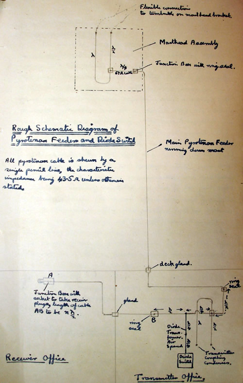
2.2 The Masthead Matching Unit
This unit which consists of three lengths of pyrotenax cable is supplied as one pattern article, assembled, sealed and mounted on a plate. The seals which were made of both seekay wax and A.R.T. compound (pitch) showed a megger reading of infinity on arrival and after some days exposure to rain, it was still infinity. A new type of sealing plug made of tufnol and fitted with a brass clamp fixing it rigidly to the end of the pyrotenax cable was used to seal the ends of the pyrotenax. This plug appears to be quite satisfactory; the insulation resistance remained at 20 megohms after a month's service at sea. The position of the main junction box (2 way with any seal) was found to be rather unsatisfactory. Instead of facing the hole in the plate, so that the cable running down the mast is brought through the hole and so to the junction box, it would be more convenient if the box was parallel to the plate, and the cable brought round in a wide sweep from the side. The general arrangement on the mast was quite satisfactory and when lowered the clearance under the Forth Bridge was 4 ft.
2.3 The Transmitter matching unit and diode switch
As the height of the office was 9 ft, the complete transmitter unit including the diode switch was mounted vertically on the bulkhead by means of brackets and cable clamps. The ends of the pyrotenax"u" piece were bent over in the form of an arch and taken straight to the coupling condensors. To avoid using large lugs which
——page break——
(3
would require excessive heat to sweat them, the fittings on the aerial side of the coupling condensors were turned down and threaded O.B.A. The metal clamps bending the centers of the "u" together was carried by a brass bracket mounted rigidly on the coupling unit. It was found that there was sufficient flexibility in the bent Pyrotenax loop to take up the vibration due to gun-fire; test were made with a 4" full calibre shoot and a 15" full calibre broadside.
The sealing of the junction boxes on the transmitter matching unit was found to be faulty and on arrival the insulation resistance was down to 400,000 ohms. These seals were made with A.R.T. compound alone no seekay wax being used and it was necessary to re-seal twice before a satisfactory seal was obtained. On future models less difficulty will be experienced in sealing the junction boxes which have to be sealed on board, as they are arranged in a more convenient position, and are horizontal.
2.4. Receiver Feeders etc.
The length of pyrotenax between the diode transformer and the receiver change-over junction base was 2 λ (26' at 40MC). As the offices were adjacent there was no difficulty in measuring the length and making it an integral number of half-wavelengths. The change-over junction box with socket, which taked the place of the former change-over switch, was mounted on a steel bracket on the top of the P.12 frame, so that it was in the gap between the receivers with the socket facing the operator. The telcothene cables were clipped round the receiver frames so that about 18" of flex was left to give a smooth hand round when the plug was plugged into the socket. A clip was provided for the plug which was not in use. The general arrangement was satisfactory and the plug and socket showed no signs of wear after
——page break——
——page break——
(4
a months continuous use.
2.5 The normal 279 equipment
The provision of stores and spare valves for the normal equipment was very bad and the situation became so serious that it became necessary to send an officer to Portsmouth to collect some essential articles personally. Even then the ship sailed with a bare minimum of spare valves. The wrong regulators were supplied with the generators and as a result they are running very hot owing to overloading. The correct regulators were ordered five weeks ago but have not yet arrived. The flexible coupling for the gyro did not arrive until three weeks after the ship left dock and had to be improvised. The general wiring of the 279 equipment itself was done efficiently, but the gunnery communications and multiphone system was hopelessly muddled and had to be put right by the ship's staff. The receiver office was well ventillated but the transmitter office was provided with an exhaust and no forced supply; as the transmitting office was below deck, the heat was at times unbearable and caused frequent sparking in the valves. The ship's staff have now supplied a fairly adequate forced draught.
On a ship such as Hood with a large and efficient staff of E.A.s it is possible for the ship's staff to correct the inadequacies of the fitting, but on smaller ships similar errors would probably be disastrous.
3. Performance and Trials
The general performance with capacity coupling was well up to standard both with aircraft and surface vessels. Ranges up to 9 or 9½ miles were obtained on cruisers of the Fiji class and were generally about ½ to 1 miles
——page break——
(5
greater than those obtained on Hood by the cruisers themselves. Escorting aircraft at 1000 ft were picked up at 28 miles and at 2000 ft at 40 miles and the average maximum range was 8 [illegible]. A detailed list of results and height calculations is given later.
3.1 The relative merits of inductive and direct capacity coupling for single aerial working.
When the transmitter is not oscillatory it is shunting the feeder to the receiver and it is therefore essential for the efficient working of the single aerial system to obtain as a high a back impedance at the transmitter as possible. Measurements showed that with direct capacity coupling the back impedance was 1500 to 2000Ω and almost non-reactive whereas with inductive coupling it was not more than 300Ω and very inductive. The aerial load presented to the transmitter was 270Ω with -5 pf (inductive) coupling compared with 14% with capacity coupling. As the ship was not in harbour for any length of time a direct comparison of the two systems with fixed echoes was impossible but tests at sea showed that capacity coupling was considerably better. Thus maximum ranges on cruisers were 6 to 4 miles with inductive coupling as against 9 to 9½ with capacity coupling and the escorting aircraft were often sighted before they were picked up.
It was therefore clear that inductive coupling was ruled out on the grounds of performance alone. Moreover the inductive coupling system was originally developed to prevent the radiation of spurious frequencies and D/F test showed that the new feeder system performed this function even when capacity coupling was used (see 3.5). It was also difficult to obtain correct loading with inductive coupling and flash-over
——page break——
(6
were frequent. It was therefore clear that capacity coupling should be used.
It was found that the removal of the insulation from the flexible coupling leads improved the impedance The coupling unit was mounted right at the top of the transmitter in order to keep the leads as short as possible. The best coupling position was just in front of the support insulator but as the aerial load was rather inductive owing to poor matching, it is probably that in future installations where the matching is correct, the coupling position will be further from the anodes.
3.2. Corrections applied to R.B./L.10.
The normal correction of -200 yds for the delay in the receiver is still required. The only other correction required was one of -100 yds being twice the length of the pyrotenax feeder in yds. No accurate calibration with the dipole was possible but the ranges obtained at sea agreed closely with those given by the directors; ranges given by R.D./F were usually between those given by the forward and after directors and there was never more than 100 yds difference between the three results. An accurate calibration with the dipole will be made as soon as possible and passed to Signal School.
3.3. The Attenuator Unit
This is no longer required in setting up RB/L10. With the improved screening provided by the concentric system the ground wave no longer saturates when the the [sic] aerial plug is disconnected, and it can be adjusted to half saturation by means of the gain control. R.B/L10 should always be fixed from the receiver.
Sunday, 20 May 2007
3.4. Spurious Frequencies.
The spurious frequencies which were known to be radiated by 279 with capacity coupling, were examined by plugging the aerial
——page break——
(7
straight into the R.B./L10. They appear as a damped train of oscillations after the R.F. pulse as shown in the sketch. Two separate frequencies are present, the strongest having a wavelength of 10 yds or a frequency of 3.3 /MC/sec and the weaker which appears as a modulation marked by the ink lines in the sketch having a wavelength of 360 yds or a frequency of 900 KC/sec. The frequencies varied slightly with the coupling conditions.
The diode switch is a non power absorbing device at 40MC, depending for its operation on the use of quarter and half-wavelength transmission lines and at these low frequencies it will absorb practically all the power from the transmitter. Moreover, the aerials are now the only part of the system which can radiate and they will not be efficient radiators of low frequencies. It seemed probably therefore, in theoretical grounds that very little in the way of spurious frequencies was being radiated by the new feeder system. H.M.S. Kenya was instructed to carry out D/F trials on 500-1200 KC/s and 2500-4000 KC/s at ranges of 4 and 10 miles. Nothing was detected on either occasion.
An attempt is being made to obtain photographs of the pulse and spurious frequencies on board H.M.S. Hood.
3.5 The Spread of the Ground Wave.
The following table gives the spread of the ground wave under various working conditions at sea.
Pulse Length |
Receiver |
Ground wave with 1 min noise |
Ground wave minimum sensitivity |
30 [illegible] |
P.11 |
4 miles |
3 miles |
" |
P.12 |
3¾ miles |
2½ miles |
8 [illegible] |
P.11 |
2½ miles |
2 miles |
" |
P.12 |
2 miles |
2500 yds (RB/L10) |
[illegible] |
P.11 |
2¼ miles |
1½ miles |
" |
P.12 |
1¾ miles |
1800 yds (RB/L10) |
These readings were taken with the aerials trained to
——page break——
(8
port. It was found that when the aerials were trained ahead, the ground wave sometimes increased by as much as 50% although there was nothing to give an echo. The increase varied with the frequency and was quite sharply directional; it seems therefore, to be due to multiple reflections between the foretop and the aerials which were on the main mast.
The P.12 receiver which is normally unstable on no load, was found to be slightly unstable when used with the single aerial system. To prevent this the first circuit was damped with a 20 K Ω resistance connected across the tuning condenser. This damping resistance made no difference to the echo amplitude.
3.6. Bearings and Bearing Transmission
The bearings were normally accurate to about 3° but the system of transmission is most unsatisfactory. An automatic bearing transmission unit has been fitted in place of the former manual one. This transmits the position of the aerials and not the position of the pointer on the dial; this would be quite satisfactory with a split phase system but to use it with the angle dividing system of 279, the aerials have to be brought to the correct bearing after this has been obtained in the normal way before the bearing can be transmitted. The delay introduced by this further operation is hopelessly long and often the 279 operators swing off the bearing before the plotting office have had time to note the bearing. The automatic transmission unit can in practice only be used by taking bearings on maximum amplitude, with a consequent loss of accuracy; moreover a third operator is required to adjust the gain control so that the echo does not saturate.
3.7. The mean anode current of the diode switch
Running the transmitted pulse the diodes conduct down and the current which they pass in the positive half of
——page break——
(9
each cycle depends almost entirely on the power output of the transmitter. Analysis shows that if the valves do not saturate and we assume a constant d.c. resistance for the diodes over the positive half of the cycle, then the following relations hold.
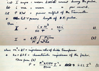
The mean anode current is easily measured by connecting an [illegible] in series with one of the leads to the [illegible] unit. The table below gives some actual results and the corresponding values of I and P as calculated from (1) and (3) above.
Pulse Length |
H.T. Volts |
[illegible] current per [illegible] |
Mean Pulse Current I |
Power |
Maximum pulse current = T I |
||||||||||||||||||||||||||||||||||||||||||
|
|
|
|
|
|
The calculated values of the power output are
——page break——
(10
in fairly close agreement with other measurements, although the last two values are probably too high owing to the fact that the pulse lengths given are too short. The figure in the last column show the probable peak current which the diodes have to give, if they do not saturate. These values are rather high, giving a peak current per valve of 3 amps. It seems probable that this is very near the saturation current of an E.A.50, so that formula (3) above probably gives too high a value for the power output. Nevertheless even though the mean anode current of the diode [illegible] does not give an exact quantitative value for the power output, it is still an excellent guide in that the mean current with a given pulse length is a maximum for maximum power.
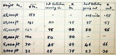
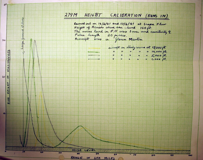
3.8. Ranges with aircraft and Height Calibrations
In the short time at Scapa it was not possible to carry out the full programme of height calibrations but sufficient information was obtained to show that the set was working well. A table of maximum ranges for aircraft flying at various heights and the corresponding height factor, K, is given below.
As the two aerials are coincident, the formula for the received signal is now
![]()
where h is the height of the aerial and ho the target height. The minimum are coincident and given by
——page break——
(11
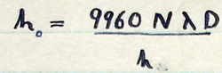
where D is in sea miles, λ in meters, h and ho in feet and N is an integer.
For the set as fitted in H.M.S. Hood, ho=160 ft and λ= 7.5 metres. The following table gives the theoretical position of the minima and some actual results.
Height |
Calculated Values |
Experimental Values |
|||||||||||||||||||||||||||||||||||||
1st minimum |
2nd minimum |
1st minimum |
2nd minimum |
||||||||||||||||||||||||||||||||||||
|
|
|
|
|
|||||||||||||||||||||||||||||||||||
Some actual height calibration curves are attached.
3.9. Ranges on Surface Vessels.
The following ranges were obtained on surface vessels.
Type |
Maximum Range |
||||||||||||
|
|
——page break——
——page break——
(12
4. Some general points and suggested improvements.
4.1 Failure of diodes owing to loss of emission
As pointed out in 3.7 the present diode system consisting of 6E.A.50 valves (VR92) is passing a peak current in the region of 18 amps, i.e., 3 amps per valve. Moreover the valves are probably saturating. After three weeks continuous running the diodes showed signs of failure due to loss of emission, the mean current falling to about half the figure given in the table in 3.7. The effect of this failing emission is to increase the resistance which in turn increases the H.F. voltage which gets through to the receiver; this causes sparking and finally breakdown in the first [illegible] in the receiver. It is possible that this particular set of diodes failed owing to overloading during tests with inductive coupling or because one of the condensors in the switch went down to earth.
Further information regarding the probably life of the diodes is expected from H.M.S. Hood. If this shows that frequent breakdowns are to be expected it will be necessary to use the new G.E.C. diode E.1248 in place of the E.A.50s. This valve which was developed for the Type 290 diode switch has an emission of at least 20 amps, tested on a milli-second pulse and its impidance [sic] characteristics are considerably better than those obtained with 6 E.A.50s.
4.2. Incorporation of a meter to read the diode current.
In the future a mili-ammeter should be included so that the diode current can be read at any time. This meter which would be connected in series with the [illegible] lead should preferably be accommodated in one of the panels of the transmitter. It would then perform the double function of providing a quick indication of the power output, which would be invaluable in coupling adjustment, and at the same time indicate failure
——page break——
(13
of the diode.
4.3. Sealing the Pyrotenax Cable.
In view of the fact that seals made with pitch only gave trouble whereas these made with seekay wax as well as pitch did not (see 2.2, 2.3) it is recommended that in the future all seals are made with both seekay wax and pitch. Full instructions will be issued with the production & fitting out drawings.
4.4. Range and Bearing Transmission.
As indicated in 3.6 the automatic bearing transmitter is unsatisfactory when used with the angle divider. It is suggested that either the old manual type should be used or that a bearing transmitter which follows the pointed should be developed. The second alternative is probably almost impossible mechanically and in general the manual method is more satisfactory as the continual swinging of the aerials is not transmitted but only actual bearings on the target.
The present range transmitter only works up to 14000 yards and ranges above that are transmitted by mult-phones [sic]. As the air-plot is usually noisy and has a large number of telephones and multi-phones to man, it is suggested that a further manually operated transmitter and receiver working up to 50 miles would be a great advantage.
4.5. Receiver Tuning.
The effect of the use of screened feeders in reducing the ground wave when the aerial is unplugged (mentioned in 3.3) is of great value in tuning the receiver. On innumerable occasions in the Atlantic it was found that the operators had no idea as to how to tune the receiver when there were no echoes present, with the result that often they failed to pick up echoes when they were present. It appears that practically no instruction in tuning is given. The following method worked well in practice and it is recommended
——page break——
(14
for the instruction of operators.
(1) Remove the receiver aerial plug and switch to short scan
(2) Starting with maximum gain, tune the oscillator stage of the receiver, adjusting the gain to prevent saturation.
(3) Plug in the aerial, turn the gain to maximum and switch to the long scan.
(4) Tune the R.F. stage to maximum noise
(5) Tune the aerial unit to maximum noise
(6) Re-tune the R.F. and aerial [illegible] using the fine control.
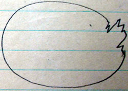
4.6. The power supplies as a source of spurious phenomena.
After some days continuous running a sort of peaky echo appeared at one corner of the elliptical scan as shown in the sketch. Similar phenomena have been seen at other times, notably by H.M.S. Fiji. On this occasion it was found that it remained when the aerial was unplugged and was clearly due to a fault in the 50 cycle power supply. This was traced to a badly scored commutator and a spot in the slip ring.
4.7. Radio Interference Suppression
The normal suppression units were fitted to the W/T receiver, but although they cut out the 50 cycles adequately they also amplified the background noise by some 300%. This amplification was [illegible] when the screen of the cable as well as the inner was connected which seems to indicate that the interference is being picked up on the outside of the R.I.S. cables and amplified.
It has been suggested by Mr. Bowman that as screened feeders are now being used with 279M, it might be possible to use a simple filter system instead of the valve suppression. This would be a great advantage with old type receivers such as those on Hood.
H.J.W. Reeves.
April 20th 1941
——page break——
SECRET
H.M. Signal School,
Haslemere.
3/9/41
Extract from Report on Type 279M installed in H.M.S. HOOD
[No M2815/40]
[See Reeves MS report 30/4/41]
Para. 3.6.
Bearings and Bearing Transmission.
"The bearings were normally accurate to about 3° but the system of transmission is most unsatisfactory. An automatic bearing transmission unit has been fitted in place of the former manual one. This transmits the position of the aerials and not the position of the pointer on the dial; this would be quite satisfactory with a split phase system but to use it with the angle dividing system of 279, the aerials have to be brought to the correct bearing after this has been obtained in the normal way before the bearing can be transmitted. The delay introduced by this further operation is hopelessly long and often the 279 operators swing off the bearing before the plotting office have had time to note the bearing. The automatic transmission unit can in practice only be used by taking bearings on maximum amplitude, with a consequent loss of accuracy; moreover a third operator is required to adjust the gain control so that the echo does not saturate."
--------------
Para. 4.4.
Range and Bearing Transmission.
"As indicated in 3.6 the automatic bearing transmitter is unsatisfactory when used with the angle divider. It is suggested that either the old manual type should be used or that a bearing transmitter which follows the pointed should be developed. The second alternative is probably almost impossible mechanically and in general the manual method is more satisfactory as the continual swinging of the aerials is not transmitted but only actual bearings on the target.
The present range transmitter only works up to 14000 yards and ranges above that are transmitted by mult-phones [sic]. As the air-plot is usually noisy and has a large number of telephones and multi-phones to man, it is suggested that a further manually operated transmitter and receiver working up to 50 miles would be a great advantage."
----------------
END OF TRANSCRIPTION