START OF TRANSCRIPTION
Page 268
ADVISORY COMMITTEE FOR AERONAUTICS.
____________________________________
Experiments on the Screening of the Bridge of
H.M.S. "Hood" from the Wind.
- By -
L.W. Bryant B.Sc, A.R.S.C.Sc. and A.S. Eatson, B.Sc.
____________________________________
March 1920.
At the request of the Director of Naval Construction a model of the bridge structure of H.M.S. "Hood" was constructed to a scale of 1 inch to the foot, and tested in the 4-ft. No.1 wind channel. The warship "Hood" attains a maximum speed of over 30 knots; and if, in addition, there is a strong head wind, it is possible that the relative wind speed over the ship may considerably exceed 60 knots (about 100 f.s.). The question of providing adequate shelter for officers on the bridge becomes, therefore, a serious problem, when at the same time an unobstructed field of view is necessary above a height of about 5-ft. from the bridge platfom. Glass screes are objectionable becase they are liable to be coated with rain or snow at critical times.
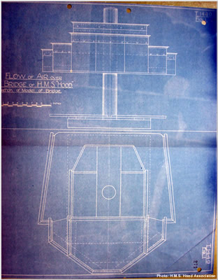
A sketch of the model is show in Fig.1. The modifications tested in the channel are marked, a, b, and c. It is understood that the narrow roof "c" would be permissible from the standpoint of naval requirements, and it will be seen from an examination of the results given in the report that this roof would also very materially improve the protection of officers on the bridge.
Page 268
- 2 -
The instrument used to measure the wind velocity was that described in T.1397. The general character of the flow was observed at low wind speeds by means of cotton streamers and smoke.
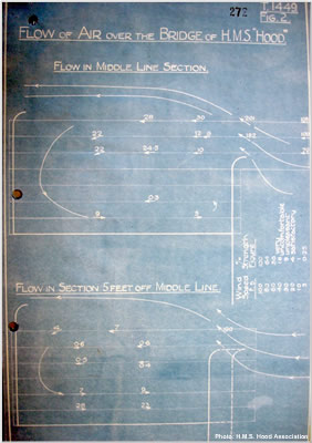
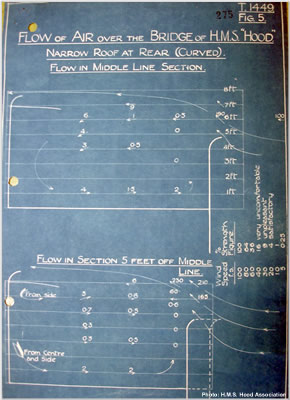
The results are exhibited in Figs. 2, 3, 4 and 5. In each case the ship's speed relative to the air is assumed to be 100 ft. per sec., and the ratio of the wind speed at each point around the actual bridge to the ship speed is assumed to be the same as the corresponding ratio for the model in the channel tested at 40 ft. per sec. The latter assumption is equivalent to neglecting any scale speed effect, and is probably a sufficient approximation to the truth for the present purpose. The numbers on the figures are each proportional to the square of the speed at the point corresponding to the position of the number, the number 100 representing 100 ft. per sec. They , therefore, give a rough estimate of the average strength of the wind at various points. It is found from experience that a wind of 20 ft. per sec. is satisfactory, i.e. it gives little inconvenience: 30 ft. per sec. is unpleasant, whilst 40 ft. per sec. is very uncomfortable. Any figure on the diagrams, therefore, below 4 indicates that conditions are quite satisfactory; but any figure above 9 or 10 is to be regarded as objectionable.
Fig. 2 refers to the case of the bridge as originally designed. Air is drawn down at the back of the bridge and runs toward the forward bulwark along the bottom. This backwash is especially strong towards the sides of the bridge, where it is reinforced by the sweeping in of air from the side bulwarks. Its energy is spent in the formation and dissipation of small
Page 269
- 3 -
eddies behinf the front bulwark. The wind is notably uncomfortable in the centre of the bridge at about head level, and about the legs to port or starboard of the centre.
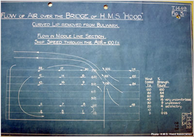
Fig.3 shows that the removal of the lip (see at "a" Fig.1) from the forward bulward makes little essential difference. There is a slight improvement on the whole, but it is at the expense of protection very near the edge of the bulwark.
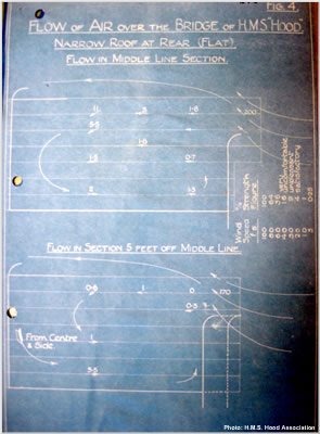
It was apparent that a roof at the back of the bridge at a height corresponding to 5 to 7 feet on the ship, and projecting as far out as permissable, must break up the air seeping down near the rear bulkhead. Accordingly, the flat roof "b" was fitted and tested with the result show in Fig. 4. The conditions now appeared to be perfectly satisfactory except immediately beneath the outer edge od the roof on the middle line. Loweing this edge as far as possible should remedy this. The curved roof "c" gave rise to the conditions exhibited in Fig. 5. The height of the edge of this roof would be 6 ft. 9 in. on the ship. There is now no unpleasant strength of air current except perhaps locally beneath the roof edge, and even here the inconvenience should not be at all serious. The shelter should be amply suggicient unless the relative wind outside is of gale strength. A beam wind may produce local currents of unpleasant strength, but they can never be of first importance, since such a wind is never reinforced by the motion of the ship through the water.
The curved lip at the top of the rear bulkhead affords no additional protection to men stationed on the higher platform behind, a straight bulwark would be just as effective. This bulwark could be increased in height by a foot or more without seriously affecting the conditions on the navigating bridge.
____________________
Accompanying Figures (click to enlarge)
END OF TRANSCRIPTION