The raison d'etre of any capital ship was her big guns - and those guns were of no use if they couldn't hit the target. This short article surveys the technology and procedures used in Hood to aim her guns, when firing against other ships. There has been growing interest in dreadnought-era gunnery during the past couple of decades (much is owed to the ground-breaking research of Professor Jon Tetsuro Sumida, especially his In Defence of Naval Supremacy), and the bibliography at the end of this paper provides a few suggestions for further reading.
Glossary
I have included these brief definitions of some key terms at the beginning, because several (elevation and deflection in particular) are fundamental. Note that throughout this article, Royal Navy terminology (which was used throughout the Commonwealth) has been used: other nations, other services used different terms to describe similar data and processes.
Bearing: the direction to the target, measured in degrees (usually red or green, ie port or starboard, respectively: eg "red 045" meant 45 degrees off the port bow).
Broadside: the simultaneous firing of all guns of a group (of the same calibre) that will bear: for example, in Hood, all eight 15-inch guns firing simultaneously, at the same target. Salvo firing, however, was the usual method.
Closing: when the range was decreasing.
Concentration Fire: more than one ship firing against the same target. Without a predefined methodology (and some practice beforehand), it was very easy for the firing ships to get confused and lose track of their own shell splashes, and thus the accuracy of their gunfire would quickly degrade.
Dreyer Range Corrector: designed by Captain John Dreyer, RA (brother of Frederic Dreyer), this was connected to the Dreyer Table to input range corrections for time-of-flight (of the projectiles), and some other values.
Dreyer Table: an analogue computer, used to calculate the gun range and deflection, which would be transmitted to the guns, and if correct, should put the shells on target. Hood was fitted with the Mark V Dreyer Table - the only vessel in the Fleet with that particular unit.
Deflection: the amount "aim off" or offset (to the right or left) needed to hit the target: exactly the same as a skeet shooter needs to aim his shotgun ahead of the target. In the RN, deflection was usually measured in knots.
Dumaresq: named for its inventor, Lieutenant John Saumarez Dumaresq, this analogue device could take own ship's speed; and the enemy's bearing, course and speed, to calculate the rate of change of range and deflection.
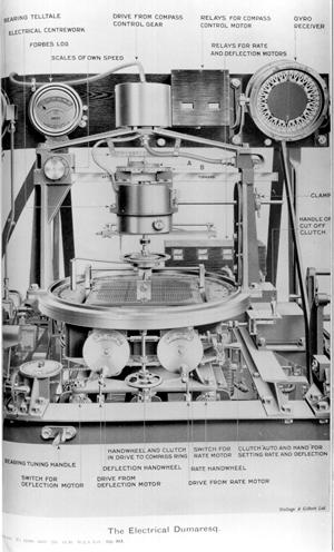
The Electrical Dumaresq, that was part of Hood''s Dreyer Table. Click to enlarge.
Source: CB1456 Handbook of Captain F. C. Dreyer's Fire Control Tables, 1918, (Admiralty Library)
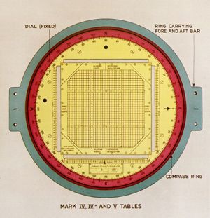
Face of the Dial of the Dumaresq. Click to enlarge.
Source: CB1456 Handbook of Captain F. C. Dreyer's Fire Control Tables, 1918, (Admiralty Library)
Naturally, the accuracy of the results depended on the accuracy of the input. There would have been several stand-alone Dumaresqs installed in Hood, for various gunnery purposes (such as the Wind Dumaresq, used to calculate the effect of wind on the shells), as well as one large Electrical Dumaresq that was an integral part of the Dreyer Table.
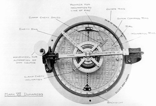
An Example of a Stand-alone (Mark VII) Dumaresq. Click to enlarge.
Source: CB1551 Manual of Gunnery for His Majesty's Fleet,Volume III, 1920, (Admiralty Library)
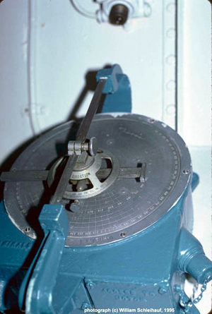
A Wind Dumaresq -- this one onboard the museum ship HMCS Haida. Click to enlarge.
(photo copyright (c) William Schleihauf, 1995)
Elevation: the angle at which the gun muzzles were raised above the horizontal (measured from the deck of the ship) so that the shells would travel the correct distance.
Error of the Day: adjustments made to account for such variables as the propellant temperature, air pressure, etc, which would otherwise cause the shells to land away from their expected point of fall.
"Follow the Pointer:" range and deflection data was transmitted to the gun positions using "follow-the-pointer" instruments, very simple in principle. Using range as an example, at the gun would be the range receiver: basically a circular dial engraved with ranges, in yards. A pointer would be moved by the range transmitter in the TS, the pointer's tip positioned against the specified range. This would cause a matching pointer, at the range receiver at the gun, to move to the same range value. In order to get the gun elevated to the correct range, the gun layer would operate a handle which would move a second pointer, so that it in turn would match the first - the movement of the handle would operate the gun elevation mechanism, moving it in proportion, so the gun would be elevated to the correct angle.
Gun Range: spotting corrections, and adjustments for the "error of the day" would be made to the range predicted by the Dreyer Table, and it would be this gun range to which the guns would be elevated.
Inclination: the angle of the enemy ship, relative to the firing ship -technically, the angle between the enemy's course, and the line-of-bearing from the firing ship to the enemy(0° when the enemy was steaming directly away; 180° when heading direction towards the firing ship). During the latter part of World War One, and between the wars, there was much interest in optical instruments ("inclinometers") to determine the inclination of the target, because inclination, if accurately measured, could be a useful input into the fire control system for determining the rates of change of range and bearing.
Layer: the (gun) layer was the crewman responsible for the elevation of the guns, and (when shooting independently, for actually firing).
MAC: Main Armament Control - using the 15-inch transmitting station, and especially the 15-inch Dreyer Table, to control the secondary battery.
Master Ship Control: in concentration firing, the preferred method was to have one ship (the "master") controlling the fire of the other ships in the group as a single unit. However, each of these other ships had to adjust their specific deflection and gun range for their unique position in the line.
Opening: when the range was increasing.
PIL: Position in Line - when several ships were concentrating their fire on the same target (and were using Master Ship Control), their own range and deflection had to be adjusted for the offsets caused by their being in a different place in the battle line than the controlling ship.
Range: the distance to the target, measured in yards. Worth noting is that the usual approximation is 2,000 yards to the nautical mile, but the correct value is 2,026.667.
Rate of Change: the rate at which the range (eg "closing 500 yards per minute") or bearing was changing over time. Note that in most action scenarios, these rates would themselves change with time.
Salvo: the simultaneous firing of a portion of the guns of a group (of the same calibre): for example, all right-hand guns of the 15-inch battery. This was the usual method of firing.
Spotting: correcting the ship's aim (both for deflection and elevation) by observing the fall of shot and making the necessary adjustments. Single shots were almost useless for this purpose: the guns needed to be fired in salvoes. There were spotters stationed aloft and in the turrets. They would independently note the fall of a salvo ("over", "short", "right", "left" "straddle") and pass that observation down to the Transmitting Station. It was next to impossible to determine the amount by which a salvo was off the target, so that standard corrections (contained in the Spotting Rules) would be used for the subsequent salvo.
Spotting Rules: a standard methodology for firing the guns and getting the shots on target, as quickly as possible. Throughout Hood's life, the Spotting Rules in use were based on those promulgated in September, 1916, embodying lessons from the Battle of Jutland. In general, these rules had the ship firing for deflection first, as it was difficult to determine overs/shorts until the shells were falling in line with the target. Rather than waiting for a salvo to land, making corrections, and then firing again, the ships would fire doubles: two salvoes seconds apart, each with slightly different settings - when firing to get the range, they would form a "ladder": the two halves of the double being separated by a known amount (eg 400 yards).
Straddle: when the shells fired as a salvo land on either side of the target. Straddling was actually the Gunnery Officer's goal: it was very difficult to actually see a hit, particularly if the shells were bursting behind armour. Moreover, straddles maximised the probability of getting a hit. When straddling the target, statistically, some of the shells should actually have been striking home: perhaps 30%.
Trainer: the (gun) trainer was the crewman responsible for traversing (training) the gun/gun mount right and left.
Transmitting Station: (usually abbreviated "TS") a compartment, located below decks and behind armour (in Hood, the 15-inch TS was on the Platform Deck, 9 levels below the revolving Director Hood) that housed the Dreyer Table and other apparatus used to control the ship's guns. It got its name from the fact that originally, the TS was the point from which orders and data were transmitted to the guns.
How it was Done
For Hood to hit the target, it was necessary to predict where that target would be, relative to Hood, when the shells would land. Fundamentally, all that Hood needed to know was the current range to the target, and the rate at which it was changing, as well as the bearing (and rate of change of bearing) of the target:
- -the target would be selected (usually by the ship's Captain), and indicated to all gunnery control positions: the exact bearing of the glasses through which the observer was looking was transmitted to Evershed receivers.
- -rangefinders, mounted in the turrets, and aloft, would be trained on the target, and gather the range data and transmit it below to the Transmitting Station, where it was plotted on the Dreyer Table.
- -the director-sight, mounted in the Director Tower, would be pointed directly at the target and transmit the bearing below to the TS.
Own-ship course (from the gyro compass) and speed (from the Forbes log) were also collected. It is important to note that the bearing was acquired much more accurately than the range; usually ships were able to put their salvoes "on" for deflection much more quickly than for range.
At the heart of the TS was the Dreyer Table, where most of this data was put together. The following figure (click to enlarge) shows the data flow for both the Gun Range and Deflection.
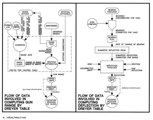
(Copyright (c) W. Jurens/International Naval Research Organization 2001, reproduced by permission)
Looking first at how the gun range was derived:
- the Dumaresq (that was part of the Dreyer Table) was set with Hood's own speed and course, the bearing to the enemy, and estimated enemy speed and course. With these values, the Dumaresq would compute the rate of change of range.
- the ranges observed by the rangefinders were plotted on the Dreyer Table. As will be seen below, as the individual readings came in, it was easy to determine an "average" range value.
- the Range Clock was set with an initial value for the range to the target, and be adjusted with the range rate from the Dumaresq. This "clock" would then output, in real time, the predicted current range to the target.
- both the rangefinder ranges, as well as the predicted range (from the Dreyer Dumaresq) would be plotted on the same sheet of paper, and if they diverged, it was easy to adjust the Dumaresq range rate from the rangefinder plots. Note that the TS would suggest a new range rate, to the Range Officer (stationed aloft, where he could see the enemy himself), but it was only the Range Officer who had the authority to order a new range rate value to be put on the clock. This was a way of verifying the rate of change of range against what could be actually seen.
- the predicted range (ie from the Dumaresq) would be adjusted with various spotting and other corrections (eg "up 200 [yards]") at the Spotting Differential. The output of the Spotting Differential was the gun range.
- an operator would be read off the gun range from the spotting differential, and transmit it to the director sight in the Director Tower (it would also be echoed to secondary range receivers at the guns and various gunnery stations).
- at the Director Sight within the Director Tower, the gun range from the TS would be applied to the Director Layer's telescope, moving it up or down as the range changed. The Director Layer would look through this telescope, keeping it centred on the target. The angle of the telescope (combining both the gun range and the motion of the telescope as the Director Layer compensated for the roll of the ship - he kept his telescope, and ultimately the guns, level as the ship moved) would be transmitted to the guns.
- the gun layers, at the guns, would use the follow-the-pointer range receivers to follow the motion of the telescope of the director sight, and thus elevate the guns correctly.
- when all was ready, the Gunnery Officer would order "shoot!" and the Director Layer, aloft, would pull the trigger and fire the guns electrically.
In summary, range/bearing data were received from aloft and calculations made on the Dreyer Table in the Transmitting Station. The resulting gun range was transmitted to the Director Sight, and the elevation to the guns.
Deflection was processed in a similar fashion:
- the bearing of the target was transmitted from the Director to the Dreyer Table.
- input from the gyrocompass corrected the bearing for yaw, and were plotted on the bearing plot, from which was read the rate of change of bearing, and from which the deflection was derived.
- the deflection from the bearing rate, and the deflection indicated by the Dumaresq, could be compared, and the correct value was input to the Deflection Totaliser.
- also input to the Deflection Totaliser were such data as wind speed, projectile drift, and spotting corrections. The total deflection (always using knots) was then transmitted to the Director.
- at the director, the deflection (ie the sum of all corrections necessary to "lead" the target) was combined with the current bearing to the enemy and the resulting training transmitted to the training receivers at the guns.
Hood was only fitted with radar in the early part of 1941, when she received a Type 284 gunnery set: at this point in the war, it would have provided another set of inputs (particularly for range) into the fire control system, but otherwise no significant change to the overall fire control system.
Fire Control Equipment in Hood
(from Table 10 in John Roberts' Anatomy of the Ship: the Battlecruiser HOOD)
15-inch tripod-type director: one per 15-inch Director Tower
Open director sights: one in each 15-inch gun house
Evershed bearing transmitters: one in 15-inch Spotting Top, two on fore bridge, two in 15-inch Director Tower
Rangefinders: 30-foot – one in each turret; one in Director Tower; 15-foot – one in the aloft Director Tower
Dumaresq: one in the Control Top
Dreyer Table Mk V: one in the 15-inch Transmitting Station
Range clocks: one in 15-inch Spotting Top, two in 15-inch Director Tower
5.5-inch pedestal type sights: one in each 5.5-inch tower
Evershed bearing transmitters: two in 5.5-inch Spotting Tops, two in 5.5-inch Director Towers, two on fore bridge
Evershed transmitters for starshell: two on fore bridge
Rangefinders: two 9-foot (replaced by 12-foot after 1924)
Dumaresqs: two in Spotting Top; two in 5.5-inch Director Tower
Fire control clocks (Type F): two in 5.5-inch TS
Range clocks: two in 5.5-inch Spotting Tops
Torpedo Control torpedo deflection sights, Mark III: four on fore bridge, two in conning tower, two in after torpedo control tower
Rangefinders: three 15-foot. After 1940, the former 5.5-inch 12-foot rangefinders were used to control the torpedo armament
Dreyer Table: one in Torpedo TS (removed 1929-31 refit
The Dreyer Table
Click to enlarge.
Source: CB1456 Handbook of Captain F. C. Dreyer's Fire Control Tables, 1918, (Admiralty Library)
Developed in the years before the Great War by Frederic C. Dreyer (a gunnery specialist, who retired as a full Admiral), this analogue computer was at the heart of the fire control system. Its driving principle was the plotting of range against time: the slope of that line gave the rate of change of range. It must be stressed that for all the criticism of the Dreyer Table (both then and now), it actually worked: this was indeed an elegant way of getting the range rate, but as of the point-in-time when those rangefinder ranges were plotted. In some scenarios, that rate would differ, sometimes quite substantially, from what it had been a few moments previously. Nevertheless, the next generation of British fire control computer - the Admiralty Fire Control Table (AFCT) - also plotted rangefinder ranges against time as a means of establishing the range rate.
The version of the Dreyer Table fitted in H.M.S. Hood was the Mark V: the final design of the table. Only Hood, and the gunnery schools at Chatham, Portsmouth and Devonport, received this particular model (it would also have been installed in Hood's sisters, Anson, Howe and Rodney). This model had all the enhancements that war service had driven, but as you can see from the accompanying illustrations, the overall design had become cumbersome. At the end of the First World War, it was decided to completely redo the design of the fire control computer, and the end result was the AFCT, which when it first appeared, was probably the most advanced of its kind in the world (the article by Dr John Brooks, noted in the bibliography, describes in great detail the design history of the AFCT).
The following plan (click to enlarge) shows the basic design:
- -the left hand-side was primarily concerned with the deflection arrangements
- -the right hand-side with range
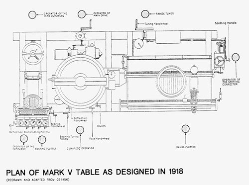
(the Mark V Table was 10' 2" long // 4' 3.5" wide)
(copyright (c) W. Jurens/International Naval Research Organization 2001, reproduced by permission)
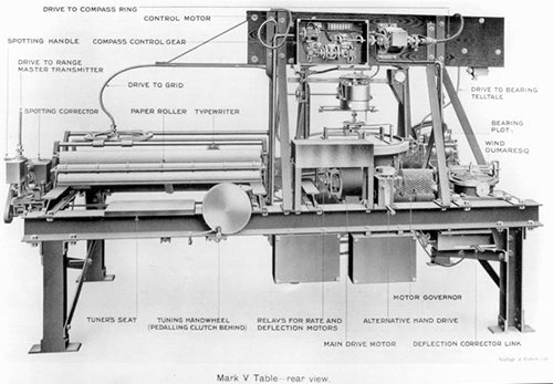
Mark V rear-view, right-hand side. Click to enlarge.
Source: CB1456 Handbook of Captain F. C. Dreyer's Fire Control Tables, 1918, (Admiralty Library)
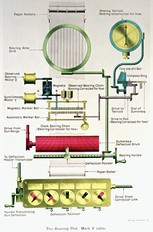
The Original Bearing Plot. Click to enlarge.
Source: CB1456 Handbook of Captain F. C. Dreyer's Fire Control Tables, 1918, (Admiralty Library)
The figure above shows the original (c1918) method of determining the bearing rate. The round bearing rate grid, visible top-centre, followed the same principle as the range plot:
- range-finder ranges were plotted as they were received; the 'x' axis being the range, the 'y' time (the paper travelled, as shown in the accompanying figure, along the 'y' axis). In the Mark V, the scale of the plot was 600 yards per inch, the paper speed being 1 inch per minute. In 1918, the plot allowed ranges between 2,000 and 29,000 yards.
- a line was drawn through the various rangefinder ranges: it was the eyes (and skill) of the operator that decided where the mean of the ranges lay, disregarding those which he considered to be seriously in error - something which would have been extremely difficult to do mechanically, using the technology of the day.
- overtop of the range plot, was the range-rate grid: by lining up one of the grid wires so that it was parallel to the line drawn through the ranges, it was a simple matter to read-off the rate of change of range.
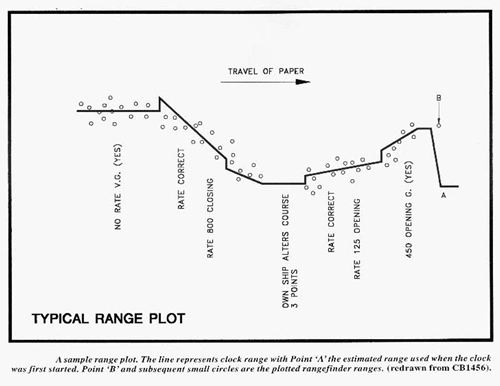
Sample Range Plot. Click to enlarge.
(copyright (c) W. Jurens/International Naval Research Organization 2001, reproduced by permission)
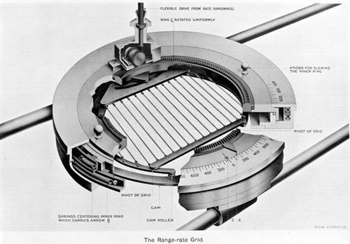
Range Rate Grid. Click to enlarge.
Source: CB1456 Handbook of Captain F. C. Dreyer's Fire Control Tables, 1918, (Admiralty Library)
The basic operation of the range clock was simple, and easily understood by those who are old enough to remember vinyl phonograph records... imagine a disc turning at a constant number of revolutions per minute. The outer edge travels much faster than the inner portion of the disc. In the range clock, there were rollers in contact with the disc, that were rotated by the motion of the disc: the speed (and direction) of rotation of the rollers depended upon where on that disc they were touching. Those rollers caused a long screw (the clock range screw) to revolve, and mounted at the right-hand end of that screw was a pencil which marked on the range plot.
In the 1920s and 1930s, additional equipment was incorporated into all marks of the Dreyer Table, the general schematics of the Mark V (circa 1930) looking as follows:
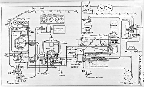
Mark V Schematics, c1930. Click to enlarge.
Source: BR938 Guard Book for Pamphlets on Dreyer Tables, 1930, (Admiralty Library)
When Hood was ordered, it was intended that she be fitted with Turret Tables: stripped-down versions (roughly 5 feet long, a little over 2 feet wide) of the Dreyer Table in each 15-inch turret, and four such units were ordered. Should it have been necessary for the turrets to go into local control (ie work independently from the centralized fire control system, possibly as the result of action damage), these Turret Tables, using ranges from the turret's rangefinder, would have allowed the turret a reasonable degree of accuracy. The Turret Table was made up of a range plot, range clock (driven by the turret dumaresq), spotting corrector and gun range counter. However, at time of writing there is no solid proof that Hood's 15-inch turrets were actually fitted with the Turret Tables. John Roberts has discovered Confidential Admiralty Fleet Order 1068, dated 10 May 1934, which instructs capital ships, except Nelson and Rodney to land their Turret Tables because "a turret type Dreyer Table is no longer considered a requirement." Were Hood not fitted with the tables at this point, her name would most likely have been excluded along with Nelson and Rodney. Manuals from 1930's indicate that British battleships had the tables, but there is no mention of battle cruisers. It is worth noting that the "Fire Control Requirements Committee" report (dated 1921: reference ADM 116/2068 in The National Archives) would recommend: centralised control positions in turrets are not required and turret local control is reduced to the simplest possible. Additionally, John Roberts (in his Anatomy of the Ship volume) notes that until 1929, there was a Dreyer Table in Hood's torpedo TS. This may have been a Turret Table.
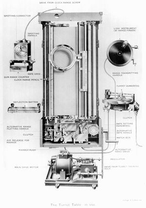
The Turret Table, of the type ordered for Hood (but not necessarily fitted). Click to enlarge.
Secondary Armament
Hood's 5.5-inch armament did not have a dedicated Dreyer Table for its own fire control solution. Instead, it used the "pre-Dreyer" system of dumaresqs and range clocks to handle the calculations, but like the main battery, communications were routed through the 5.5-inch Transmitting Station, located on the Lower Deck, adjacent to the lower conning tower and Torpedo TS. The facilities were sufficient to cope with two simultaneous targets (typically one port, one starboard).
If the 15-inch guns were not in action, it was possible to use the Dreyer Table in the 15-inch TS: it could be switched over to "MAC" (Main Armament Control [of the secondary armament]), and so control the 5.5-inch gunfire in the same fashion as it would for the main armament.
Transmitting Station
The following diagram (click to enlarge) shows the layout of Hood's 15-inch Transmitting Station, circa 1930:
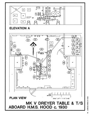
(Copyright (c) W. Jurens/International Naval Research Organization 2001, reproduced by permission)
(Copyright (c) W. Jurens/International Naval Research Organization 2001, reproduced by permission)
Acknowledgements
I am grateful to Allan Harris and Bill Jurens, of the International Naval Research Organization (http://www.warship.org), for granting permission for the use of the drawings by Bill Jurens, originally in the three-part Warship International series, "The Dumaresq and the Dreyer" (Numbers 1, 2 and 3, 2001). I am also grateful to John Brooks and John Roberts, who were each kind enough to have a look at a draft of this article, and their suggestions are much appreciated - naturally, any errors are the fault of the author.
Bibliography
Brooks, John. "Percy Scott and the Director", Warship 1996, David McLean and Anthony Preston (editors) (London: Conway Maritime Press, 1996).
Brooks, John. "The Admiralty Fire Control Tables", Warship 2002-2003, Anthony Preston (editor) (London: Conway Maritime Press, 2003). This is an important paper, with much information on the Dreyer Table as well as the Admiralty Fire Control Table (AFCT) that was fitted in later RN ships.
Brooks, John. "The Mast and Funnel Question: Fire-control positions in British dreadnoughts 1905-1915", Warship 1995, John Roberts (editor) (London: Conway Maritime Press, 1995).
Brown, D. K. The Grand Fleet - Warship Design and Development 1906-1922 (Annapolis: Naval Institute Press, 1999).
Friedman, Norman. Battleship Design and Development 1905 - 1945 (New York: Mayflower Books, 1978).
Padfield, Peter. Guns at Sea (London: Hugh Evelyn, 1974).
Raven, Alan and John Roberts. British Battleships of World War Two (Annapolis: Naval Institute Press, 1976).
Roberts, John. Battlecruisers (London: Chatham Publishing, 1997).
Roberts, John. The Battlecruiser HOOD (London: Conway Maritime Press, 1982). Part of the Anatomy of the Ship series, to date the ultimate technical description of this famous ship.
Schleihauf, William. "The Dumaresq and the Dreyer," Warship International (Toledo Ohio: International Naval Research Organization) Number 1, 2001 (Part I); Number 2, 2001 (Part II); Number 3, 2001 (Part III).
Sumida, Jon Tetsuro. In Defence of Naval Supremacy - Finance, Technology and British Naval Policy, 1889-1914 (Boston: Unwin Hyman, 1989).
Sumida, Jon Tetsuro (editor). The Pollen Papers (London: George Allen & Unwin, for the Navy Records Society, 1984).
Sumida, Jon Tetsuro. "The Quest for Reach: the Development of Long-Range Gunnery in the Royal Navy, 1901-1912," Tooling for War - Military Transformation in the Industrial Age, Stephen D. Chiabotti (editor) (Chicago: Imprint Publications, 1996)