Boilers, Fuel & Related Equipment
Boilers: Steam was supplied by 24 Yarrow Small Tube 3 Drum Boilers, which burned oil fuel. There were six of these boilers in each of the four boiler rooms. The working pressure was 235 lbs psi, and the heating surface per boiler was 7,290 feet². These required extensive and frequent cleaning to remove scaling.
Fuel Oil: Hood carried an average load of approximately 1,200 tons / 1219.3 MT of fuel oil. Maximum load was 4,000 tons / 4064.3 MT.
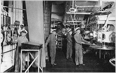
Above- Hood's forward engine room
Boiler Room Fans: Each boiler room was fitted with 6 fans and engines. The fans had cylinders 9 inches in diameter by 7 inches in stroke. They were of the enclosed forced-lubrication type.
Pressure Pumps: There were 16 oil fuel pressure pumps, with four being situated in each boiler room. These were all 12 ton pumps except for the two in the foremast boiler room, which were 24 ton pumps and were used for transferring oil fuel as well as for feeding the fires.
Main Steam Pipes: The main steam pipes were arranged in two runs along each side of the ship in the boiler rooms. These carried steam from each boiler room. They were of 19 inches bore and were connected to the engine room through two combined bulkhead and emergency valves on each side of the ship They were also cross-connected in the forward engine room. This cross-connection allowed steam to be channeled to the manoeuvring gears in each of the forward engines. Addditionally, branches 19 inches in diameter ran to the Middle and After Engine Rooms. There was a separator fitted between the steam pipe and regulating valve on each engine.
Funnels: Hood was fitted with two funnels. Each served two boiler rooms. Each funnel e measured 25 feet deep by 18 feet wide, with an outer casing at a distance of six inches from the funnel proper. The distance from the lower burners on the front of the boilers to the funnel top was about 100 feet.
![]()
Brown-Curtis Geared Turbines
Hood was equipped with four sets of turbines. Each turbine served one propeller shaft. The port and starboard outer shaft turbines were located in the Forward Engine Room. The port inner shaft turbine was located in the Middle Engine Room. The starboard inner shaft turbine was located in the Aft Engine Room.
Each set consisted of compound ahead turbines which drove propeller shafting through single reduction gearing. There was also a Brown-Curtis type cruising turbine that could be used for cruising speeds. This had a separate casing and could, when necessary, be connected to/disconnected from the main high pressure turbine shaft. Each turbine was complete in itself with its own condenser and auxiliaries, and could be operated independently of the other turbines. The turbines featured the following components:
Rotors:
Each high pressure ahead turbine rotor consisted of ten wheels, of which the first and second were velocity compounded, having two rows of blades each and the remainder were simple impulse wheels. Each low pressure ahead turbine rotor consisted of eight wheels, of the simple impulse type. Each cruising speed rotor had four velocity compounded wheels with three rows of blades on the first wheel and two rows on each of the others. The astern turbine for each shaft was incorporated in tile low pressure ahead turbine casing and consisted of two velocity compounded wheels, each carrying three rows of blades.
Casings: The turbine casings were of cast iron with the nozzle control valve seatings cast into the body. The rotor spindles were of forged steel, having a tensile strength of 34 tons to 38 tons per square inch. The wheels were of forged steel, of similar quality and phosphor bronze was used for the blades, which were of the usual impulse type. The blades had dovetailed roots, and the tips of the blades were supported by phosphor bronze shrouding. The diaphragms were of cast iron with the nozzle blades of nickel steel (about 3.5% nickel) cast in. The diaphragms in the cruising turbines were solid, the remainder of the diaphragms in the high pressure turbine and those in the low pressure turbines, being split. The spindle was made steam-tight where it passed through the diaphragms through the use of segmental serrated brass rings, kept up to their work by garter copper coated steel springs in the cruising and the first diaphragm of the high pressure turbines, as well as by sheradised coach springs in the other diaphragms of the high pressure and in the low pressure turbines. The glands were packed as was usual in Brown-Curtis turbines with carbon rings made in segments and held in position by springs. The high pressure ahead forward end gland had eight carbon rings and the astern turbine four rings. The cruising turbine was fitted with five rings in each of the glands.
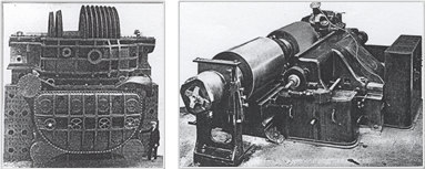
Above/Left- Low pressure & reverse turbine with condenser;
Above/Right- Set of geared turbines
Condensers: The condenser for each set was hung beneath the low pressure turbine and had a total condensing surface of 24,400 feet². The tubes were 5/8 of an inch in external diameter, 0.048 inches thick and 12 feet 3.5 inches long between tube plates. The total number of tubes per condenser was 12,144. The condensers were of the Weir's Uniflex type with shells of steel plates and angles, the steam entering directly from the low pressure turbine and flowing through the condenser, while the circulating water passes through the lower tubes first and then the upper tubes, The condensers were designed to give a vacuum of 28 inches with sea water of 55° F, and a barometer at 30 inches. The weight of a condenser with the tubes filled with circulating water was about 70 tons.
Performance: The engines were designed to develop a total horsepower of 144,000, with about 210 revolutions of the propeller and about 210 lbs pressure in the control chest, with 28 inches of vacuum in the condensers.
The high pressure turbine made 1,500 R.P.M. at full power and the low pressure turbine made 1,100 R.P.M.. Single reduction gearing was employed to reduce the revolutions of the turbine shaft to that of the propeller shafting. The pinion driven by the high pressure turbine was 20.174 inches in diameter at the pitch centre, while that driven by the low pressure turbine was 27.51 inches in diameter. The gear wheel had a pitch circular diameter of practically 144 inches. These wheels were of the "BUILT" type and weighed about 46 tons apiece. There were 392 teeth in the wheel- 55 on the high pressure pinion and 75 on the low pressure pinion. Hence, the ratio of reduction was 7.127 for the high pressure pinion and 5.226 for the low pressure pinion.
![]()
Additional Equipment
Thrust Blocks: The thrust blocks on the rotor spindles (which also acted as adjusting blocks for the rotors) were of the Michell type, as were the thrust blocks on the propeller/screw shafting.These latter measured 4.5 feet outside diameter of collar, with thickness of collar of 7.5 inches. This single collar took the whole thrust on the shaft. The white metal surface of each thrust block amounted to 1,176 inches² both ahead and astern, giving as pressure on the thrust surface of about 200 lbs at full power ahead. The thrust shaft was 24 inches in diameter, the intermediate shafting 24 inches in diameter and the propeller/screw shafting 28.5 inches in diameter.
Circulating Pumps: Each set of main engines was provided with two main circulating pumps, the engines being of the enclosed forced-lubrication type, and each pump had a 30 inches suction, 31.5 inch diamater impeller, two duel air pumps, the steam cylinder being 20 inches in diameter by 20 inches stroke, the wet pump 36 inches diameter by 20 inches stroke, and the dry pump 38 inches diameter by 24 inches stroke; Two grease extractors of the gravitation type, a direct contact feed water heater, two forced-lubrication pumps and one water service pump.
Auxiliary Condenser: There was an auxiliary condenser in each of the Middle Engine Rooms as well as the Aft Engine Room. Each condensor had 5,390 tubes and a condensing surface of 5,330 feet². These worked in unison with two auxiliary air circulating pumps. The pumps were of 18 inches suction and discharge and 27 inches diameter impeller.
Miscellaneous Pumps: For the plummer blocks, a forced lubrication pump and a water service pump were fitted in the Aft Engine Room for the plummer blocks. Additionally, the engine rooms were equipped with six fire and bilge pumps, four oil fuel tank pumps, a general service air compressor and four fresh water pumps.
Distilling Machinery: The distilling machinery was situated in the Middle and After Engine Rooms. There were two sets ("A" and "B") in each engine room. Each set "A" consisted of two 80 ton evaporators and one distiller. This combination could be used for supplying water for the ship's use or make-up feed water for the boilers. Each set "B" consisted of one 80 ton evaporator with a vapour pipe connected only to the auxiliary condenser in the engine room in which it was situated. This was used purely for boiler make-up water.
![]()
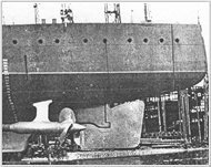
Screws/Propellors & Shafts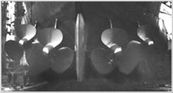
Screws: 4x three bladed Manganese Bronze screws
Screw Diameter: 15ft / 4.57m
Screw Weight: 20 tons apiece
Shaft Diameter: 28.5in / 72.4cm
Shell Bracket Weight: 35 tons each
Notes:
- Screws turned outwards when driving the ship ahead (clockwise on starboard, counter-clockwise on port)
- Designed screw revolutions per minute was 210 rpm at full speed. This permitted the adoption of propellors of higher efficiency.
- Originally designed 210 rpm. Achieved 206 rpm at full speed on trials in Feb/March 1920.
![]()
Steering/Conning
Steering Gear: The steering gear was of the right and left-handed screw type. They connected with rods attached to a crosshead on the rudder head.
Steering Engines: Two steering engines were situated in the after engine room. Each consisted of three cylinders, with direct acting engines 17" in diameter by 14" stroke, worked by a hydraulic telemotor. These connected to shafts which reached aft to the steering gear. For auxiliary steering, there was a Williams-Janey type electro-hydraulic variable speed motor in the after steering compartment. It was also connected to a telemotor.
Rudder: Single rudder, mounted on centreline. This worked best using ample power and prop wash from the inner two screws. To learn more, read Notes on Handling the "Hood".
Conning Positions: The ship could be directly controlled from the following positions:
- Conning Tower
- Lower Conning Tower (Emergency position)
- After engine room
- Steering compartment (auxiliary only)