
Box art for the Trumpeter kit
Background - Trumpeter and Us
Trumpeter models of China has the distinction of marketing the most kits of Hood in a variety of scales. Their first model was their 1/350 scale offering. This was followed a few years later by two 1/700 scale variants of the ship (one as sunk and one as in 1931). In the these cases Trumpeter sought to create the most accurate kits of Hood then known. To that end they consulted numerous documents and web sites. They also enlisted the help of the HMS Hood Associations web site staff.
We reviewed plan/profile drawings and annotated corrections for any major errors we found. We also provided detailed photos to verify and confirm our corrections. We weren't able to catch everything, plus Trumpeter was unable to make all corrections work due to engineering, production and budgetary concerns. Despite this, the 1/350 scale kit, while not perfect, was still the best kit yet released up to that point in time. The process repeated itself when the 1/700 model was planned...but by that point we had learned even more about Hood as sunk. We relayed that information to Trumpeter and much of it was added to the model. This meant that the 1/700 scale 1941 Hood ended up being probably the most accurate (at least of the affordable/commercially produced variants) model of the ship yet produced.
That was several years ago, and since that time we've learned even MORE about Hood's final configuration. So, naturally, when we heard Trumpeter was considering a 1/200 scale Hood, we tried to relay the latest configuration updates to them. Their response was a bit surprising: the representative was quite terse with us and said something to the effect of that he thought 'it was supposed to be perfect the first time.' The impression given was that he seemed to think that since Hood was a FAMOUS ship, then it MUST therefore be very well documented. That's an incorrect assumption of course: The reality is that Hood in her FINAL configuration was NOT as extensively well documented as she was earlier in her career. We often see "new" things that simply do not fit with what was previously assumed about the ship...and we've seen enough to know that even her official plans are incomplete or erroneous in places.
To make a long story short, Trumpeter did not want our help. Instead, they appear to have relied upon detailed plans from one or more eastern European monographs on the ship. Said publications are beautifully drawn and largely correct, but each has its share of inaccuracies both minor and major. These likely came about through a combination of incomplete/dated source materials, misinterpretation of plans, a lack of access to key detailed photos and records and several erroneous deductions stemming from a lack of familiarity with the ship. So, the monographs end up being a mix of both good and bad...and this model is the same. The sad thing is that by using those materials AND listening to us, Trumpeter could have had, at long last, the perfect kit. Not that this kit is "bad"...well, more on that below.
Of course, its no use crying over spilt milk...some might even say we're lucky to have any kits in this scale at all. So, its time to stop ranting and get on with the actual review!
Packaging & Kit Contents
The box top art is absolutely stunning: it depicts Hood at sea with Prince of Wales. The kit box itself is very large and sturdy with dimensions of approximately 55" x 15.75" /140cm x 40cm in size. This outer box contains a compartment for the hull and three small boxes (listed as A, B & C) containing the various parts and components. Also included are very detailed instructions, a (flawed) painting guide, and a few advertisements. Very tough and impressive packaging.
The kit itself consists of 1490+ parts. The plastic portions are moulded in light grey styrene. These include a one piece hull (@52" / 1318mm in length!), about 17 sprue trees, and four large deck sections. There are also some smaller styrene parts in plastic bags. The plastic components are all crisply moulded with minimal flash and sink holes. An interesting feature of this kit is the fact that many key structural components are moulded complete as sub-assemblies. These include large sections of the bridge, both funnel bases, the after concentrating position and the internal amidships focsle deck structures. In other words, many main components are ready to add right from the box.
In addition to the styrene parts, Trumpeter also includes 7 frets of nice quality photoetch. These include railings, ladders and stairs, deck fittings, boat parts, gun parts, funnel parts and both starfish platforms (which are ONLY in photoetch for this kit. There are no styrene starfish). They also include some metal rods (prop shafts), anchor chains and waterslide decals. This is enough to build a very nice representation of the kit.
Important: This kit is a true multi-media kit. What we mean by this is that its not just a plastic model with optional photoetch for additional detail. In reality, photoetch is used as an integral part of the model's structure. In fact, there are major structures that are nearly 100% photoetch. The two most notable examples are BOTH starfish platforms. Trumpeter also engineered assemblies that are intentionally made up of both plastic and photoetch. In other places they intend for photoetch to complete key portions of shipboard equipment. SImply put, you have to used photoetch in order to complete major portions of this model.
At the time of writing, this kit (Trumpeter item 03710) is available worldwide from numerous retailers at a price of @$300 US. The actual price will vary based on demand, location, shipping, etc.
Overall Impression
In typical Trumpeter fashion, this appears to be a decent model when built straight from the box. The moulding and detailing are excellent, and the end product still looks convincingly like Hood despite the many errors/flaws (some minor, some quite prominent, but nothing insurmountable) present in the kit's details. Many of these could have been easily avoided had Trumpeter consulted the proper sources. For such an expensive kit, it could and should have been better.
This kit isn't for everyone. First, its LARGE. Second, its a bit expensive (and some will have to spend even more money on aftermarket detail sets). Third, it requires a certain degree of proficiency with photoetch (photoetch is integral to the model- the kit cannot be built without it). So, if you have the space, money, and don't mind working with photoetch, this kit is for you! If not, then perhaps you should consider Trumpeter's 1/350 kit instead.
For those of you who choose to build this 1/200 kit, please be advised that there is plenty of room for improvement; If you have some degree of modelling skill and take your time, you can turn this kit it something quite good. Don't feel like you HAVE to improve it though - build it the way YOU want it. If you are happy with the model the way it is, then that's what counts. So, only do what you are comfortable doing. .
In the rest of this article, we'll be covering various key kit components that could benefit from modifications/corrections. We will differentiate between major and minor problems and suggest ways to make improvements. To aid in this, we will provide, where possible/practicable, kit step and part numbers. We will also provide textual and photo links to annotated images and other reference materials. So, please be sure to click on all images and text links.
Corrections & Suggestions for Improvement
Hull
 Hull Plating- The one piece hull appears to be largely accurate in form. Unlike the 1/350 kit, there is no easy option for a waterline variant (you'd have to manually cut-off the lower hull). The hull is more detailed than previous kits; With the exception of the hull's very bottom, most key plates are represented. The plating, as is common in plastic models, is somewhat over-scale/exaggerated in depth. For example, the thickness of various thinner bow and stern plates measure in at the scale equivalent of 3" / 76mm or more. This is a relatively minor issue that most folks can ignore. Those of you who wish things to be in scale can consider lightly sanding/scraping the raised areas and/or filling the recesses with built-up paint, putty or styrene strips (just be mindful that it can be difficult to keep things uniform). Click here to see a photo of the bow plates on the actual ship.
Hawse Pipes & Anchors- There are four of these on Hood, three on the bow and one at the end of the stern. Trumpeter included holes in the bow openings, but failed to do anything for the stern. This is a key item that can be easily added by any modeller- as part of Step 1, simply measure the distance and drill an appropriate sized hole in the edge of the stern. The bow hawse pipe openings are acceptable, but could be more accurate; Modellers may wish to correct the shapes and even connect the openings in the hull sides to the openings in the deck. Tubing, built up foil,clay, putty, resin or even styrene could possibly be made to work.
The anchors (Steps 25 & 26, parts E67), appear to be mostly accurate. Detail-minded modellers may wish to use aftermarket anchors, but the kit parts will be fine for most modellers.
 Hull Scuttles/Portholes- Some of the hull scuttles/portholes on both the bow and stern seem to be very slightly out of position. The differences are minimal, so the average modeller can simply ignore them and leave them as-is. It is however, an easy fix for those who wish to make corrections - fill in any erroneous holes with plastic rod and/or putty, then mark and drill new holes in the correct locations.
For added detail, you can add the the little "rain gutters" known as rigols above the new holes. You could also add bars to the appropriate windows near the anchors. We recommend doing any filling and drilling during Step 1, but do not add rigols or details until after completing the degaussing cable/coil mentioned immediately below (due to the work involved and the close proximity of the elements on the hull). Click on the image to the right to see the bow's correct scuttle/porthole arrangement. Click here to see the correct scuttle/porthole arrangement for the stern.
 Degaussing Cable/Coil- The location of the cable is correct, but the shape/course it follows is a bit "off" here and there. It also suffers from being exceedingly plain and simple. We strongly recommend that modellers carefully remove the moulded on cable and replace it with an aftermarket brass photoetch cable or built-up strip styrene. Its relatively easy to cut/scrape it off and sand it smooth (just watch the hull angles and try to avoiding gouging things). Its a key feature and certainly worth the effort. We recommend that this be done early in construction (during either Step1 or Step 2) as you may have to "manhandle" the hull a bit when removing the cable. The information below will help the modeller understand Hood's degaussing cable arrangement:
The actual ship had substantial cables fitted in a double, single, double arrangement. They were secured to the hull using rectangular fasteners. These were evenly spaced where possible. For the most part, the cable followed the same line as the deck immediately above. This was problematic on the bow and stern though- due to interference from other structures, the course of the cables had to be altered a bit. More on this below:
 Bow - Her bow was fitted with dual cables (the upper one being slightly narrower in height than the lower). These extended rearward until roughly abreast "B" turret. The bow cables were unable to follow the deck line for their entirety; they had to be routed around protruding structures such as the clump catheads and anchors. This resulted in the cables beings slightly "wavy" and the fasteners being misaligned and unevenly spaced in some areas. In other words, the cable looked a bit "sloppy" on the bow of the actual ship.
To help keep the cables away from the bow anchors, Hood was fitted with two fairings directly over the side hawse pipes. Both were stepped in appearance with the starboard side one being longer. Each had a small cut-out for a fairlead (note- the starboard side only had the fairlead cut-out above the forward/active hawsepipe). See the image to the right for the specific shapes. The railings are in green, the degaussing cable in blue and the stepped fairings are in red. This is a very easy fix- simply cut or file a step-down into each fairing. Its also possible that aftermarket photo etch sets may include fairings.
- Amidships - At roughly "B" turret it became a single cable which ran aft until reaching the point somewhere abreast of "X" turret. This was neatly applied and its fasteners were regularly spaced. The only slightly odd section would be where the cable passed literally outside of the large "gash chutes" on the side of the ship.
- Stern - From roughly "X" turret back, the stern was encircled with dual cables (just like the bow). The fasteners were relatively evenly spaced and neat in appearance. Trumpeter (and most other models and drawings of Hood as sunk) depicts the degaussing cable as "dipping down" for a small distance abreast the rear turrets on both sides of the ship. In reality, this is only partly correct: like the bow, the two sides of the stern did not precisely match. Photos of the ship's portside DO show such a dip, however, footage of the starboard side shows no dip. So, we advise fitting a straight piece of cable in that location.
Bow Chute - Hood carried a chute on the port side of her hull/bow roughly abreast the capstans. This can be easily added using plastic strip stock filed to shape.
Rudder & Propellers/Screws - These appear correct in shape and form. We've been informed by one model builder that the kit instructions have the propellers reversed. We haven't had time to verify this, but are still advising builders to check this closely before attaching the propellers to the model.
Decks (From Front to Back)
Focsle Deck - This deck comes in two parts which are added in Step 2: The first piece (referred to as the "Fore Deck" in the kit instructions) reaches from the bow to roughly just past the bridge. The second piece (referred to as the "Center Deck") runs from there back to the forward portion of the quarterdeck. When assembled in place, the seam is cleverly hidden under the forward portion of Hood's shelter/boat deck. Detailing is good, but one key item that can be improved are the three deck openings for the hawse pipes. The shapes are not quite right- they are too oblong and tapered at the forward end (the actual openings were more proportionate and even...more like rectangles with rounded corners). Despite this, most people can live with them as-is. Detail-minded modellers may wish to drill these out and reline with styrene. Again, it might be good to include the actual hawse pipes. If using aftermarket photoetch, remember to NOT put covers on all three openings. As sunk, only the rear (unused) starboard opening had a grated covering!
The focsle area could be made more detailed by adding the various deck devices which were mounted on this area of the ship. This includes "clump catheads," paravane streaming devices and sounding platforms. Various skylights, lockers and hatches can also be improved upon with aftermarket photoetch. Both breakwaters (Steps 19 & 20, parts A11, A40 through A45) could also be detailed with a strip around the top. We also recommend replacing the supplied anchor cable/chain with aftermarket chain (try to use one with a centre stud).
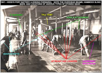 Side Batteries/Enclosed Focsle Deck - This refers to the area featured in Steps 5, 6 and 7. The general shapes of the structures are correct , but the area is missing numerous details both minor and major. Since this area will be difficult to see after completion, many people may choose to live with it as-is.
Detail-minded modeller may wish to tackle the following: First, the kit is missing the large bollards located in these areas (one on each side of the ship). These can be added with plastic card and tube stock. Second, the large columnar supports for the outer rear 4" gun mounts P3/L3 and S2/R3 are missing. These can be added with tube styrene (consult kit Parts 21 to determine the correct size). Third, the many slim support pillars are missing (several on each side of the ship). These can be added with thin metal or plastic rods (you will have to drill into the deck and ensure you cut them to the right height.
There are also numerous other small details that could help improve this area: One could drill-out portholes, add/update various missing or misplaced doors, sliding windows and vents, plus add hoists, lockers, hammock sling bars, pipes, vertical stiffeners (where applicable) and racks. For ultimate detail, one could even add the under-deck girders which supported the boat deck overhead. For placement reference, we recommend you consult the ship's plans or John Roberts' excellent "Anatomy of the Ship - the Battlecruiser Hood."
Shelter Deck/Boat Deck - This large chunk of the model is the kit's "centre stage" so-to-speak. It comes into play during Step 8. The kit instructions refer to it as the "Up Deck." Its very crisply detailed but needs a fair bit of work to become truly accurate; Analysis of recently rediscovered photos of Hood have shown that the previously accepted shapes of all all four UP and five of the seven 4" gun emplacement splinter shields/bulwarks are slightly incorrect. These new finds actually affect all known drawings, books and commercially-produced models created up to now. Fortunately, most of the needed changes should be easy to accomplish:
 Deck Plating (Corticene) - The kit shows a great deal of what appears to be rectangular deck plating. In reality, this corresponds to @6x12 foot sheets of corticene (a brown coloured linoleum-like material) with raised metal strips along the borders. Hood carried this arrangement until at least mid 1940. The decking along the sides of the deck (under the various secondary guns and rockets) had its corticene removed and replaced with "semtex" (a very rough non-slip coating). We know (from 1941 photos) that there was still some corticene in use at the time of the ship's loss.
To reflect this change, we recommend filling-in the small panel lines of the outer section of the deck (see the image to the right). Additionally, there are incorrect mounting holes in the deck just forward of each forward UP launcher splinter shield/bulwark. These are meant to help mount two sets of three small boxes. In reality, these boxes were not present on Hood. So, these holes should be filled-in.
 All Boat Deck UP splinter shields/bulwarks - New photo analysis has proven that the tall/raised sections of UP splinter shields/bulwarks were slightly different in layout and shape- namely that the shields were three levels in height rather than just two as shown in the kit: Starting at the front, the two forward UP shields need to have two "steps" added to their forward facing segments. This means that the outboard section of shield (which was a bit over 4 ft tall on the actual ship) steps up about two feet in height after crossing a few feet inboard. This raised section extended a few feet further inboard and then it rose again by approximately another 2ft. This tallest portion wrapped around to the rear of the shield where it dropped back down to the lowest height. As moulded, the kit only accommodates the first two levels...its not quite tall enough to accommodate the highest section. At its highest point, it measures about 9mm tall, which scales to 5.9 ft. This is fine for the first step-up in height, but to replicate the next step-up (the highest segment) it will be necessary to add a strip of styrene about 3mm or so in height. Some photoetch producers may also make replacement shields to cover this modification. See the photo to the right for the general layout.
 P1/L1 & S1/R1 4" splinter shields/bulwarks - The splinter shields/bulwarks that protected the two forward most 4" mounts are slightly misshaped. This again is something common to all drawings and commercial models of Hood produced to this point. Trumpeter depicts both shields as being level with the deck. This is not correct; The shields actually rose up in height slightly as Recent photo analysis on the actual ship, the shields rose up slightly as they went outboard. In addition to this, the forward inboard shield segment was also not level. It rose sharply up to a point. The port and starboard shields were mirror images of one another. Many modellers can live with this as-is, but detail minded modellers will wish to correct it. To do it absolutely right, it may be necessary to remove the entire shield and replace it with styrene or aftermarket photo etch shields. The correct shape of the splinter shields/bulwarks is illustrated in the photo to the right.
The two rear boat deck UP splinter shields/bulwarks are also "close but not quite right." The problem again refers to the tall/raised curved inboard section of the shields. The height is fine, but the shape is slightly incorrect: All drawings and models show these as being centred/aligned with the lower/outer flat portion of the shields. This was not the case on the actual ship; Recent photo analysis has proven the raised sections to be positioned with their centres slightly more forward. This can be easily mended by careful snipping and/or filing.
- P3/L3 & S3/R3 4" splinter shields/bulwarks - Another notable error are the long splinter shields/bulwarks abreast the rear pom-pom bandstand, rear superstructure and the nearby 4" gun mounts. Interestingly, Trumpeter got these features right in their previous kits! The main problem is that there is an extra segment of shield (angled inboard at the rear of each outer segment). This simply did not exist on the actual ship. There was a long single/straight shield on each side of the ship. The other problem with the shields as moulded in the kit are the profiles- Trumpeter moulded them as flat/horizontal to the deck. In reality, when viewed in profile, the shields rose to a slightly pointed peak in the middle.
Overall, this is a very major error and we strongly recommend modellers make some changes. At a minimum we recommend cutting off and removing the sections of shield that angle inward. You may need to re-scribe the deck afterwards (unless you plan to use a wood veneer replacement deck). Detail minded modellers can likely remove the entire shields and replace with a correctly-shaped replacements in styrene or photoetch.
 Number 4 (rear/centreline) splinter shield/bulwark - The splinter shield/bulwark that enclosed the rearmost 4" mount is incorrectly shaped. It was not a "U" shape...it was actually flat at the very rear and had small angled shields on its forward corners. Like the shields mentioned immediately above, this too was previously correct in Trumpeter's 1/350 and 1/700 kits. Of course, this is a fairly common mistake for many other models and drawings of Hood. It likely stems from the fact that the ship's official plans are incorrect (not all modifications made to Hood were accurately recorded) and due to a lack of detailed photos being available until only fairly recently (in fat, we only re-discovered the correct shape after several previously unpublished photos came to light in the early 2000s).
This is a major error, and we recommend modellers take steps to remedy it: Proficient modellers should be able to fix this by removing the rear portion and replacing it with a flat segment of styrene. The forward edges also need to be trimmed back a bit . From there, the angled forward edges can also be added with styrene. This can also be addressed with aftermarket photoetch splinter shielding.
- Portholes Above Torpedo Tubes - The portside area above the torpedo tubes is incorrectly configured. The numerous small portholes (to the officers' heads) are missing entirely. Trumpeter included too many standard sized portholes. This is easily remedied by marking the correct positions and drilling out the piece with correct sized drill bits. Some of the existing holes may need to be filled first though. Fortunately, the starboard side looks okay. Trumpeter had the same problem with their 1/350 kit, albeit reversed.
Quarterdeck- This part is referred to as the "Rear deck" in the kit instructions. Its largely correct in shape and layout. The only possible suggestion here is to correct the shape of the stern through-deck hawse pipe with styrene (it should be more oval in shape) and drill it out. It could also possibly be connected to a newly-drilled hawse pipe on the rear edge of the hull.
Additionally, we recommend not using part A57 (step 28). The cross deck boom and guest warp boom are not believed to have been fitted in 1941. There was also no sign of them on the wreck itself (the end of the stern was found to be in very good condition in 2001, 2012 and 2015).
Armament/Guns
 15" Main Gun Houses/Turrets- The kit comes with 6 main gun turrets. This gives the modeller two extra turrets to practice on! The turrets are generally correct in overall size and shape. Overall, they are a vast improvement over Trumpeter's earlier 1/350 scale kit.
The one notable (and consistent) problem with the gun houses are the directors (Step 70, Parts H3 & H4). They are actually well detailed and with the intended photoetch are quite accurate overall. A notable problem still remains- the shape of the outer edges/caps. As moulded, they are from much earlier in Hood's career. These will need to be reshaped. See the photo to the right for the correct shape.
Another feature missing from the turrets are the bevelled edges where the forward side and front armour sections joined. These bevels were on the lower edge of these areas. These are easily added with careful filing. See the photo above/right for the exact locations and shapes. One other easy-to-add detail is the armour plate that was below the rear of each turret's gun house. Simply cut sheet styrene to match the outline of the back half of each gun house. Detail minded modellers may also wish to add the various awning attachment points to "A" and "X" turrets.
The kit doesn't differentiate between turrets very well. Just remember to use the turrets with rear vents on "B" and "X" barbettes. Be extra careful in Steps 70 through 74: Remember that step 70 shows "A" turret on the left and "B" turret on the right. Note that "A" turret's director "wing" has notched rear corners (H43). As for "B" turret, its actual gun house had notched lower rear corners. These can be easily added by carefully filing the lower rear edges. Step 71 shows "X" turret and Step 72 shows "Y" turret.
We recommend replacing the 15" gun barrels with metal replacement parts. They will look much better at this scale.

- "X" Gun House Platforms- Replace these (parts H1 and H2). You can use the provided photoetch support brackets, but discard the actual plastic platforms. These were not flat, solid, angular platforms on the actual ship...they were originally two identically sized frameworks (when viewed from above, they were made up of square segments with X cross beams in the centre of each square). Each "platform" consisted of three such squares and they are both directly inline with each other. The only reason one appears smaller than the other is because of the changing shape of the turret beneath them. This causes a bit of an optical illusion. By 1941, the frameworks did not reach to the corner of the gun house. Click on the photo to the right to see the correct configuration.
- "Bridge" on "X" Gun House- In addition to the aforementioned platforms/frames, there was also a small "bridge"/platform permanently attached to the upper rear/centre of X gun house. This allowed access to/from the rear of the turret and the very end of the boat deck. This was in place for several years before the sinking.
Twin 4" Secondary Armament- These seven mounts (parts G3, G10, G18, G19, G29, G30 & G32) appear correct in size and shape. You can make these far more realistic by incorporating aftermarket metal barrels and other details with additional photoetch or wire.
UP Rocket Launchers- The five UP launchers are quite detailed and are made up of both plastic and integral photoetch parts. The only issue we see are the splinter shields/bulwarks (raised "walls") that surround all five UP launchers.
 "B" Turret UP- This piece (part B7 in step 71) is shaped incorrectly. Hood's "B" turret UP platform was not a large rectangle supporting a central circular area. In reality, there were three connected platforms. There was, of course, the circular "tub" in the centre and this connected (at the front edges) to two smaller "ready use" platforms. These were half the depth of the circular section and provided just enough space for a ready use locker and a walkway/working space.
The circular portion of the deck is incorrect in that it is has a splinter shield/bulwark with a uniform height (see photo to the right). In reality, the real splinter shield/bulwark encircling the base was not uniform in height. It actually doubled in height for short spans directly to port and to starboard. Click here to see additional views of the correct splinter shield/bulwark arrangement.
This feature has been known of since the mid 1970s, but was usually overlooked in most models and many drawings. It was overlooked in the 1/350 kit, but we made sure Trumpeter included it in the 1/700 kit. Sadly they overlooked it for the 1/200 scale model. Fortunately, this should be easy to correct by simply adding some correctly shaped (and curved) sheet styrene to the applicable locations on part B7. Otherwise, we are hopeful that one of the hoped for future aftermarket detail sets addresses this need.
- Boat Deck UP Positions - All four locations require slight changes to the shapes of their splinter shields. This was already covered in "Decks" above.
Pom-pom Anti-Aircraft Guns- The three pom-pom gun assemblies (Step 69) are each made up of about 13 styrene parts combined with additional photoetch. They appear to be highly detailed and mostly accurate. The only thing they are somewhat lacking are certain portions of the manual sites that sat above each unit. It might be possible to scratch build these or to replace elements (or the whole mounts) with existing aftermarket photoetch for other ships. Additionally, those into serious detail have the option of replacing each individual gun barrel with turned metal barrels. Please remember that Hood's pom-poms did not have conical flash suppressors! Overall, its not absolutely necessary though as the kit parts will be enough for the average builder.
0.5" Machine Guns- These four machine gun mounts (Step 39) are also generally correct. The actual guns consist of 6 plastic parts with photoetch shields. There are a couple of things to be aware of when assembling these items:
- Forward Guns- ("Pip" and "Squeak") are mounted on the Conning Tower (bridge). Do not add the photoetch shields to these guns.
- Rear Guns- ("Paul" and "Simon") the guns sat atop pedestals (parts E57). Trumpeter moulded two small boxes onto the base. In reality, only one box was on each base (the other was mounted on the deck inboard of the pedestal).
You should indeed use the photoetch shields for these two guns.
Those wishing to incorporate additional detail should consider adding angled braces and access ladders to the base pedestals.
Forward Superstructure/Bridge
Bridge Base/Admirals Signal Platform- (Step 9, part L2). This piece is large and well formed, but some shortcuts were taken in production. Mainly, Trumpeter closed off some open area at the lower rear and upper front of the structure. There are also some missing substructures and recent configuration re-discoveries to address.
 Area Beneath 0.5" MGs - Trumpeter failed to realize that the area directly below the two 0.5" machine guns was actually open at the rear. They chose to model this as solid/enclosed. This is incorrect as the inset within the photo to the right demonstrates. In order to fix this, its necessary to cut away the vertical pieces (shown in red and green in the image to the right). From there, it would be necessary to add bulkheads and decks adjacent to the newly opened areas. This can be done with sheet styrene. In addition to this, modellers should also add a single, slim columnar support beneath each machine gun mount. This can be easily done with brass or plastic tube.
Overall, this amount of construction may be difficult for inexperienced modellers. An alternative would be to "shade" the area using a dark (black or very dark grey) paint...this may or may not help mimic the fact that it was an open space. Its difficult to tell how well that would work at such a large scale. If you do choose to cut-out the area, we recommend you do so before doing any other bridge work (as it will involve "man-handling" the bridge).
 Lower/Rear/Underside- Trumpeter only moulded the rearmost edge of the base structure beneath the rear of the signals platform . This is perfectly understandable as its very difficult to see into this area once the kit is built. Even so, detail minded modellers may wish to cut this out and build it up using styrene.
Additionally, modern photo analysis has revealed that the area behind and beneath the extended rear of the signals platform was extended and partially enclosed in Spring 1940. Basically, a splinter shield/bulwark was added to the rear corners of the bridge - it followed the same line/angle as the lower bridge walls until reaching the rear of the newly extended signals deck overhead. At that point, each side turned inboard for a few feet. This small segment was curved just like the deck above. This is a very notable modification and we strongly recommend modellers add it. It should be a fairly easy addition by using styrene/plastic card. We recommend doing this in Step 9 but AFTER any 0.5" Machine Gun area work and BEFORE gluing parts B3 in place. The photo to the right shows the shape of the extensions.
- splinter shields/bulwarks - The raised splinter shields/bulwarks along each side of the Admirals Signal Platform are acceptable as-is, but detail minded modellers may wish to make them more accurate. One key way to do this is to match the correct profile as the actual ship: As moulded, the shields are the same height. In reality, Hood had two slightly lower segments in her shields (both sides of the bridge). These areas were where the saluting cannon were once attached. When the Admirals Signal Platform was extended in 1939, these lower portions were left as-is. A series of stanchions and a top railing were added outboard of the splinter shields. To correct this, simply file down the areas and then rebuild the "rail" and any damaged stanchions using tube styrene or very thin wire. Click here to view an image showing the location of the lower areas.
 Splinter proof Shelters- These are missing from the kit. We had told Trumpeter about these structures during the development of their 1/700 kit. Unfortunately, Trumpeter appear to have overlooked them for this new 1/200 scale kit. These shelters were added to the real ship in Spring 1940. There were two such shelters-one to port and one to starboard located between the rear rear portions of the Conning Tower Platform and the HACS Mk III* pedestals (Step 45, parts E36).
The omission of these structures is a substantial error, but one that can be remedied fairly easily. It should be possible for modellers to build up reasonable facsimiles of these shelters using sheet and strip styrene and detailed with photoetch elements: The shelters should go from the deck to just beneath the actual HACS (leave room for the HACS to rotate. There will be a small door in the shelter's rear very close to the HACS pedestal. The image to the right shows the location and shape of the starboard shelter (in yellow). The port shelter would have been a mirror image.
 HACS Mk III* Directors- These (step 45, parts E32, E36, F47 & F53) are are very nicely done, but are not quite as accurate as they should be. There is one notable error that affects part F53- the part is moulded with a rounded cover in the centre. In reality, Hood's final HACS Mk III* did not use a dome-shaped canvas cover: By 1940/41, her three directors each had metal-plated tops. When not in use, these could be covered with a much smaller, form-fitting canvas tarpaulin. Unfortunately, this will require major surgery to correct, so many modellers may choose to leave it as-is, or, seek out aftermarket replacement parts. Click here to view an official schematic of the director's exterior (note- disregard the domed cover shown in the drawings...this was not present in Hood's three directors.).
- Bridge-Mounted Carley Floats (rafts) - (Step 9, parts G33) Trumpeter mistakenly tells modellers to mount two floats to each side of the lower bridge base (part L2). This is incorrect for Hood as sunk. It is true that she did carry floats in those positions for several years, but they were repositioned in 1941. At the time of her sinking, she carried one float on each side of the lower bridge centered above the three wooden booms (parts E64 and G31). The other two floats were mounted abreast the first funnel. This is easy to correct: simply ignore the instructions, fill-in the mounting holes with putty and consult this photo for placement.
 Conning Tower Platform- (Step 46, part L1). Beautifully moulded but only partially correct in appearance. The shape (from overhead/plan view) is a bit off...the actual ship's conning tower was a bit more narrow to the front. Of course, this is something most people won't notice and can easily live with (besides, it would be extremely challenging to correct). Detail minded modellers could add a bit more definition by adding a pipe across the top/right. Others may wish to cut out the viewing slits for a more three dimensional effect (personally, I'd just paint the slits black). The rigols above the view slits are a bit soft...it may be beneficial to replace them with wire or photoetch pieces in order to add more definition.
The very rear of this platform is another story- it doesn't follow the correct deck shape. There are also raised shields where there shouldn't be. This area will have to be cut and filed into the proper layout. Any missing portions can easily be recreated using styrene stock. Additional detail can be added (if so desired) in the form of underside supports, pipes, cables, water tanks, etc. See the image above/right for the correct layout.
Another detail missing from this area are the outcroppings where the foremast tripod legs passed through the lower edge of the Conning Tower Platform supports and into the Admirals Signal Deck. These can be created by cutting a bit of tubing at an angle, then shaping to fit. Before this can be done however, it will first be necessary to correctly re-shape the rear of the deck (see the image above/right for layout).
 Admiral's Bridge Deck- (Step 52, Part B39). Though this piece doesn't technically follow the exact shape of the deck on the real ship, it will be sufficiently close for the vast majority of modellers. Those of you wishing to correct the shape can consult the image to the right; if you look closely you'll note that the rear of the part is too symmetrical (this area was actually longer on one side than the other aboard the real ship). You'll also note a slight difference in shape near the front quarters.
Another (albeit minor) missing element is the triangular "cut-out" in the deck near the rear/port side. The edges of the opening are surrounded by guardrails. The purpose of this opening in the deck is not known to us, but it is clearly present in the plans and in photos taken as late as 1940.
Otherwise, the only noticeable error on this part is the splinter shield...its the same height all the way around the piece. On the actual ship, this shield was raised in height at a point just past the front of the Admiral's Bridge superstructure. This part could realistically be left as-is, but some modellers may wish to correct this problem by raising (or replacing) the splinter shield/bulwark aft, or slightly filing down the forward portion (though this runs the risk of making that section too low). The very rear center portion of the shield should be removed. This segment had metal railing.
Upper Bridge Platforms- These parts are shown in Step 52 of the kit instructions. These decks have various issues, some major, some minor. For many, they will work as-is, but for those who want a truly accurate model of Hood, there are things which must be addressed. The three images below/right highlight the changes which need to be made to this area:
 Forebridge - (Part B40). This is reasonably close in appearance, but it does have a few minor issues to correct. Near the front are the ladder ways for reaching the Compass Platform. While these are closer to being correct than earlier models of Hood, the openings are a tad too far forward. These could be lengthened at the rear and filled at the front if one wishes them to be precise.
The other issue with this part are the pom-pom director extensions. These were the prominent oval shaped areas at the outer rear corners of the Forebridge. On the actual ship, these were stepped down a couple of feet lower than the main Forebridge deck. They were also enclosed by inboard metal shields (which were the same height as the Forebridge splinter shielding). This section of shielding can be seen in the image to the right. The kit part does not reflect the step down and it lacks the inner portion of the shield.
There are two possible approaches to mending these errors: First, the oval sections could be cut off and reattached slightly lower. The missing splinter shield/bulwark can be created with styrene or even extra photoetch. Aftermarket photoetch could also be used. For most people however, it may be easier to leave it as-is and simply add the inner shields with styrene. One could possibly make them look lower by painting the deck inside the extensions a darker grey. One other important detail missing from this section are the ship's main signaling lights. These large items were very prominent and should be added to the front section of each pom-pom director extension. Use plastic stock or aftermarket photoetch to replicate these lights.
 Torpedo Control Platform - (Part B6). This piece has several issues that need to be corrected. On the actual ship, this platform was not level with the upper portion of the Forebridge. It was actually situated two feet higher. There was also a transverse splinter shield/bulwark that divided them. Crew accessed the Torpedo Control Platform from the Forebridge by climbing a very short stair and passing through a swinging door in the splinter shield. This is a feature that no model kit has ever gotten right. We strongly recommend making corrections to this area as it is the central focal point of the model. At a minimum, we recommend people add the transverse splinter shields/bulwarks and small steps.
The outer rear portion of part B6 is incorrect. The rear corners were not rounded, but angular (and stepped up slightly). The outline of the very rear edge of the deck is also not correct. This is correctable through careful cutting, filing and use of styrene.
 Compass Platform - (Top front portion of part N4). The upper row of windows is where the Compass Platform is. This is where VADM Holland and Capt Kerr commanded the ship from during it's final battle. Its also the location from which survivors Ted Briggs and William Dundas escaped. We had previously helped Trumpeter to get the window arrangement correct for their 1/700 kit, but the information was overlooked for this kit. The main problem here are the two windows at the very top/front. Hood carried this arrangement until late 1940/early 1941 when it was changed. As sunk, Hood had a single large window flanked by two small windows in this area. It may be possible to fix this by cutting out the center frame and inserting strips of styrene in the correct locations. We are hopeful that an aftermarket parts company will release photoetch or resin replacement parts to address this error.
 Torpedo Control Position - (Top rear portion of part N4). This is generally correct in layout, but the small platform just forward and to the sides of it is incorrectly shaped. This platform was longer and shaped differently. It was used to reach the two Air Defence Positions atop the bridge. It was reached via a ladder from the Torpedo Control Platform deck. From there, crew could walk into the two AD positions. There are two windows missing from the front face of this section (there should be one window in each front corner). This area can be detailed by correcting the platform shape with styrene, drilling/filing out windows (to include adding the missing windows), installing photo etch rails and by adding voice tubes (using wire or thing plastic strips).
- Air Defence Positions - (Parts B8 and B12). Trumpeter mistakenly added a splinter shield/bulwark to the rear of part B8. This was not present on the actual ship. This should be removed and replaced by railing. Part B12 is mostly accurate, but is lacking the wind baffle that surrounded this structure. It would be worthwhile to recreate this using styrene strip or photoetch. We are hoping that an aftermarket parts producer will eventually create this in photoetch or resin.
 Foremast Structures- The foremast is a somewhat complex mix of integral photoetch and styrene parts.
- Foremast Starfish Platform - The kit's foremast starfish platform itself is made up of several detailed photoetch parts. When assembled, it attaches to the Control Top (part N3) above and the upper terminus of the foremast tripod legs (part B10) below. When assembled, it looks quite nice, but unfortunately, the brass portion of the starfish platform has serious configuration errors: In plan view can see that the front protrusion is missing as are the large, rounded rear corners. Additionally, when assembled and viewed from the front, the side under supports taper to a point, but on the real ship these had been truncated and were squared off at the ends. This configuration has been well documented for several years now. The correct shapes are illustrated in the image to the right. Note how some of the features were seen on Hood's wreck in 2001.
 Control Top (aka Spotting Top)- This (Step 51, Part N3) is nicely moulded and has a few minor issues, but overall is sufficiently accurate for the average modeller to use as-is. Detail-oriented modellers may choose to correct the issues with a few minor modifications (see the photo to the right): The most notable issue is the omission of the small platform used to access the roof and radar. This can be seen as an inset in the photo to the right. This was previously correct in Trumpeter's 1/700 kit but they left it out of this new kit. This of course can be easily added with styrene and photoetch. Another issue is the lack of roof overhang around the upper forward section of the part. Hood had been modified with such a feature by 1941. Another issue is at the point where the upper forward and lower rear windows roughly align - there were no angled back windows at the ends of the upper windows. Additionally, the window ledges are not as well pronounced as they were on the actual ship. Another slight issue is that the vertical walls are not quite as angular and panel-like as those on the real ship. Again, due to scale, this will not matter to most modellers.
 Radar Director Hood- (Step 50, Parts B14, 15 & 18). Part B15 is incorrectly shaped: Trumpeter moulded a small box on the port rear side of the director. This is an age-old mistake commonly repeated in drawings and other models of the ship (with the exception of Trumpeter's 1/700 kit). There was no box here; for years, plans had been based upon partial photos and an optical illusion. On the actual ship, the roof was raised slightly in the left rear corner. With the exception of this one area, the outer dimensions of the director remained the same. This can be seen in the rough schematic to the right. The area in red and yellow is the raised section of roof.
This can be corrected by removing the small "box" from the left rear of part B15. Fill-in the hole that remains. The raised portion can be built up using styrene (or perhaps re purposed from the plastic box that was previously removed). As for the actual Type 284 gunnery radar, the antennae are in nicely moulded photoetch. They appear to be accurate, but detail-oriented modellers may wish to further compare the parts to photos of Type 284s aboard Hood and Prince of Wales.
- Tripod Legs - The upper rear legs of the tripod mast (Step 55, Parts E16) are acceptable as-is for most modellers. Those striving for additional detail may wish to improve upon the legs. This can be done by adding additional detail for the cable trunking. This covered a sizeable portion of the outward-facing portions of the rear tripod legs. This could be potentially be accomplished with sheet and strip styrene or carefully applied foil. The kit does appear to be missing the lowest portion of the forward tripod leg (where is passes abaft the structures on the lowest two platforms). This is something even aftermarket detail sets generally miss, but modellers can easily replicate it with styrene tube or brass rod.
Amidships/Aft Structures
Funnels- The funnels (Steps 56 & 57) and their based are nicely moulded and detailed. The funnels themselves include rivet detail as well as key integral photoetch components (internal walkway, funnel stays, cage top, etc.). There is, however, a MAJOR problem (in fact, the worst issue of this kit): Trumpeter moulded the rear funnel too small. They made it a bit smaller in diameter than the fore funnel. This is not correct. In reality Hood's funnels were essentially identical. There was no size difference. Of the two funnels, the fore funnel (parts C15, C6, C7 & C4) is closest to being correct. The rear funnel problem affects parts C14, C16, C17, C3 and related photoetch. Although the size difference is quite noticeable, some modellers may choose to ignore this. Otherwise, some may wish to enlarge the rear funnel pieces by cutting the various segments vertically and adding extra styrene. Of course, fit of the integral photoetch may then be an issue. It may also be possible to part source another front funnel and components. Fortunately, Pontosmodel has addressed this problem with their superb super detail set. So, many modellers can simply choose to go with Pontosmodel's part(s).
Detailed-oriented modellers may wish to add the small patch that added to the second funnel due to splinter damage incurred at the unfortunate action at Mers el-Kebir. Another detail to look out for is the bakery flue (Step 56, Part C2). In reality this did not run up the outside of the funnel, but pierced it low (possibly through the base) and vented inside.
 Funnel Bases/Large Vents - These are nicely moulded but can benefit from additional detailing: For example, some modellers may wish to hollow-out the long engine room vents and augment them with photoetch (when an aftermarket producer eventually produces some). Additionally, modellers may wish to consider adding the extra lumber stores that were atop BOTH funnel bases. The kit is lacking these details.
- Forward Funnel Base - (Part M2). We believe there was at least one lumber/stores rack to port of the first funnel's base. This is accurately reflected in the kit as part B4. What is missing however are the storage racks/areas atop the actual vents. The starboard side area could be screened with canvas. The portside one seems to have been metal. Carley Floats were stacked atop these areas (as well as mounted from the sides).
- Rear Funnel Base - The base of the second funnel (Steps 31 & 32, Part M1) also had screens atop its engine room vents. These screens were metal and were used to retain large timbers and other materials that were stored in the area. Modellers should consider adding the side screens using plastic stock or photoetch. There were outer as well as inner screens (to prevent the wood from spilling out onto the deck and from rubbing against the funnel itself). The large structure forward of the vents is mostly correct in shape. The forward outer corners are a tad off (they were slightly angled on the actual ship), but should be close enough as-is for most modellers.
 MF/DF Platform Between Funnels - This (Step 31, Part B50) sits atop Part M1. Details are crisply moulded and are augmented with photoetch. Unfortunately, there are four key errors to address: First, Trumpeter chose to give this a recessed roof. In reality, this structure had a flat, overhanging roof. This can be easily remedied with plastic stock or photoetch.
The second notable error concerns the aerial spreaders (Step 31, Parts E31, PE-B28 & 29). The The shape of the main/centre spreader arm is incorrect. The small upper support strut is also missing. In reality there was a large centre spreader arm supported by a brace in front, a brace behind, and a small brace from the top/centre. Trumpeter seems to have inverted the centre support. This should be an easy fix with plastic strips or photo etch.
The third notable error are the photo etch railings from Step 32. Trumpeter instructs the modeller to place safety railing around the upper/forward top of Part M1. This is not correct. In reality, there was just a short segment of rail at the very front of M1 and another segment along the rear wall of the forward portion. The outer edges were un-railed.
The last notable error are missing rafts. In 1941, Hood was equipped with numerous "Denton Rafts". These were small square-shaped rafts about 3ft across. The exact number and placement are not known...but we do not that quite a few were stowed atop the structure between the funnels (next to the MF/DF platform). We also know that they were stowed up against the gunwales along the sides of the ship. This was the very type of raft the three survivors clung to after the ship sank (they did NOT use Carley Floats as those were destroyed with the ship).
- Motorboat Workshop - This is the small structure on the upper rear of part M1. Trumpeter moulded the piece with a flat roof, too many doors, too many ladders and missing windows. In reality, the roof was slightly arched/curved, there was one ladder and one door (starboard side) and there were three very large windows on the rear bulkhead. These were sometimes canvas covered.
Interestingly, a majority of photoetch makers have assumed, wrongly, that this was actually a tall vent! We're not sure why but its yet another common mistake we see with regard to Hood. As a result, many photoetch sets include unnecessary grilled vent covers for this structure. We are sure some manufacturers will continue to repeat that mistake when details become available for this kit. If so, simply don't use the part. Of course we're left with a solid structure...to fix this one could attempt to cut-out the windows. Another possibility is to create frames with styrene. One last possibility it to use the incorrect photoetch grilles that we will inevitable see included in photoetch sets...but cut out the mesh/grilles (leaving just a frame). Lastly, one could simply try some creative painting (i.e., paint three black squares).
 Various Vents & Other Boat Deck Features - The various engine room vents and mushroom vents are generally accurate in appearance and location. The only notable error is concerns the engine room vent on the forward bulkhead of the After Concentration Position/Searchlight Control Position (part N2). This is covered later in this article. Due to the large size, all major engine room vents may benefit from being hollowed-out and augmented with photoetch. This would give them a see-through effect similar to the real vents aboard the ship.
Another item that would benefit from additional detail is the large wireless trunk near the base of the mainmast (step 37, part B47). In reality, this structure was not enclosed, it was only surrounded with a circular shield. To correct this, drill-out the center of part B47 (or replace it with a tube). Attached to this structure is a slimmer but taller trunk. The kit instructions erroneously instruct the modeller to mount this in the wrong orientation. In reality, the taller trunk should be positioned so that it is on the forward/right side of the large open lower trunk. This is easily done by simply rotating the part until the alignment is correct.
Another change that modellers should consider is the removal of both "signals tubes" (Step 14, parts E19). These were circular shaped (viewed from above) openings with hinged tops. Certain hand annotated (in 1940) ship's plans indicate that both tubes were removed in the 1940 refit. Unfortunately, we can find no visual proof in the form of photographs (there are no currently known 1940/41 photos that show these areas up close). These plans do accurately reflect other known changes, so we feel that its very likely that the tubes were removed. The main question that remains is, what happened to that deck space? Was it simply plated-over, or was is perhaps reconfigured? Its possible that the space was used for skylights, extra ventilation, hand-throughs, or even possibly an ammo hoist for the nearby pom-pom guns. Perhaps another ? We simply do not know.
 Mainmast- (Step 58). This is nicely detailed with styrene legs and photoetch starfish platform and details. As with the foremast the starfish is entirely photoetch and there is no option of using a styrene version. The assembly could use a bit more detail in the form of the star fish underside stays and the small structure atop the starfish platform. Note that the stays were used to support all but the two forward "arms" of the starfish platform.
We also recommend enclosing the outboard areas of the control platform at the base of the mast's centre leg (Part PE-B13). Photos show that this was enclosed by 1940 (sides only...the rear likely remained open).
After Concentration Position/Searchlight Control Position- This part (Steps 33 & 34, Part N2) is crisply moulded but has several very notable errors. A number of these can easily be mended, but others will require careful planning and effort. We'll cover each main issue one-at-a-time below:
 Top splinter shield/bulwark & Upper Searchlight Position Deck- At the front, note the two semi-circular corners surrounding the upper search light positions at the front of the platform. These splinter shields/bulwarks are too tall and should be reduced to half their height. Moving aft, note that there is a chequered square feature in the splinter shield/bulwark (port and starboard). This should be cut-out. In reality, there was a gap in the shield here. Add safety railing instead. The chequered boxes were actually flag lockers which faced inboard and only party blocked the openings. Next, look at the flat deck to see two hatches. Remove the one to starboard (there was only one hatch and it was to port). The only other detail to be added is a the 8" flair which was part of the splinter shield. This can be added with plastic strip or aftermarket photo etch.
- After Concentrating Position - This is indicated by the row of small windows on the upper rear of part N2. Trumpeter has moulded 8 small windows, but in reality, there were only 7 on Hood (there was a small device in the centre of the middle window which Trumpeter mistook for a frame). We also recommend adding a disk-shaped fog light immediately above the windows. It may be possible to fix the window frames by cutting them out and adding new ones, properly spaced. It could also be replaced with aftermarket photoetch (Ponotosmodel).
 Central Area - The area immediately forward of these windows is very wrong: Trumpeter moulded in a "stepped" structure enclosed by a photoetch wall to starboard (Step 33, Part PE-B11) . This was NOT on the actual ship and is only seen in erroneous drawings (based on misinterpretations of the official plans). In reality, this was all one large block as the image to the right clearly proves. Also missing from this area is the large angled support beam which helped hold up the upper platform. It could be seen between the After Concentrating Position and the centre of the main structure. They also moulded a non-existent door and ladder to the starboard side. These should be removed (along with the aforementioned "hatch" on the deck immediately above them). Click here to see the arrangement of the port side.
- Lower Rear Area - Trumpeter moulded a series of square-shaped windows around the lower rear portion of N2. These windows were indeed there for most of Hood's career, but they appear to have been plated over circa 1937. Photos from the late 1930s onward show no sign of square windows nor canvas covers. Instead, the photos seem to show that the side doors were still present but that they were flanked by a porthole on each side. The narrow rear bulkhead appears to have had no portholes. This can be fixed with careful filling sanding and drilling and sanding.
- Lower Forward Area - Part N2 is missing the bulges which were present just below the lower/outer searchlight platforms. These cab be easily added with plastic stock (or aftermarket photo etch). Another problem is the engine room vent at the lower front of N2. Its not tall enough and is incorrectly shaped. In reality, it was nearly as tall as the two water tanks which flanked it. It also had a squared top with hinged openings. The grating shape was also more angular (in the upper corners).
- Additional Considerations - Other details to consider would be to give the vertical corner edges of N2 a more rounded appearance, add voice pipes and electrical cables/trunking and drill-out the four archways/doors to the searchlights.
 "Auntie" Pom-Pom Bandstand- The bandstand (part C5, step 39 of the kit instructions) is nicely done. There are only two minor errors: First, Trumpeter mistook an ammo hoist hatch (located between the two ready use lockers) as another locker. Simply add a photoetch hatch here instead of part B28. The other error is that Trumpeter forgot to include the canvas screen that was located directly under the forward/straight portion of the bandstand. This is easily added with styrene though.
Rear Screens- These are the large vertical areas below the rear of the Boat Deck and at the front of the quarterdeck (parts C9 and C14). Trumpeter did a good job in getting the large rectangular openings correctly laid out. The porthole arrangement is quite close though a tad off. Some of the lower portholes were not positioned at the exact same height aboard the actual ship. This is something relatively minor that most modellers can live with though.
There are two key omissions from these screens: a pair of vent hoods/covers. There was one to starboard and one to port which covered the lowest set of slotted vents. See the image to the right for exact location. This can easily be created using styrene. Otherwise, both screens could benefit from additional detailing such as hose attachments, trunking, and of course, the ship's name. Much of this is available via photoetch.
Boats
The various open boats, fast motor boats and Carley Floats are notably much nicer than boats in Trumpeter's earlier Hood kits. Detailing is crisp; some of the detail is a bit overstated, some a bit understated, but with the integral photoetch parts, reasonable facsimiles can be made. In fact, each boat could very well be a miniature model in its own right! They are of course missing the aforementioned Denton rafts. These, along with life rings should be added to the model. With regard to the boats, the ship's boats were frequently canvas covered.
Painting Instructions
Trumpeter's instructions are mostly correct but have some key errors when it comes to the bridge decks and the underside of the hull (she was not red underneath...she was actually grey/black!). With this in mind, we strongly recommend you ignore their instructions and use ours instead. You can at least be sure that people have put a good deal of time into the research.
General Detailing Considerations
Here are some other general detailing suggestions:
- Replace any moulded-in plastic ladders with photoetch. It looks better at this scale. Also be sure to add any missing ladders, etc.
- Add voice tubes with thin wire or strip stock
- Add electrical cable trucking, foot holds/hand holds around key superstructure items, metal plating, rigols over portholes/scuttles, etc.
- Add under-deck support pillars and roof beams where applicable.
- Portholes/scuttles/windows can be drilled/cut-out and glazed.
- Bridge equipment (Dumaresqs, compasses, voice tubes, various sights, etc., ) can be added to the upper bridge decks (we're unsure if any aftermarket producers create such equipment at this time).
- Add the mainmast port and starboard indicators (green ball to starboard, inverted red cones to port)
- Don't over weather the ship. A little weathering goes a long way, especially considering the fact that Hood was completely repainted just a couple of weeks before she fought Bismarck. See our article on the Paint Schemes of H.M.S. Hood, 1920-1941
"Shortcuts"
If you are modelling Hood in port, then most of her boats should be uncovered. Her various deck ladders would be installed as well. If you are modelling Hood at sea, many, if not all of the boats would have been covered by canvas. Some of her weaponry such as the UP launchers and 0.5" machine gun mounts were also frequently canvas covered when not in use or when not expecting action. Additionally, her large ladders (the two alongside the forward superstructure and the four from the quarterdeck to the large side screens) would all have been dismantled and stowed. If modelling them as stowed, do remember to "flip-up" the two forward ladder top platforms. For the rear platforms, be sure to add the frameworks that supported the tops of each ladder. The model does look nicer with the ladders in place and boats uncovered, but its not necessarily realistic. The choice is yours of course.
Resources & References (Which Ones to Use & Which Ones to Avoid)
When building a detailed model of Hood, a thorough modeller should of course compile various reference materials. Of course, unless they are already familiar with Hood, they may not know which references can be trusted and which cannot. To aid in this effort, here are things you can trust (plus some you shouldn't):
Good References (Recommended)
The following items are HIGHLY recommended as use for references when building models of Hood:
- HMS Hood Association web site - This is our web site. We have many photos and detailed historical information for Hood and crew.
- On the Slipway web site. - Our good friend Evert-Jan Foeth's impressively detailed site devoted to his work at creating the most accurate model of Hood possible.
- "Anatomy of the Ship - The Battlecruiser Hood" book by John Roberts - Excellent source of detailed drawings. Please note however, that the 1941 plan view of Hood is not entirely accurate. This only because at the time the book was originally created, certain features of Hood were not known or confirmed. Everything else is excellent.
- "Hood Design & Construction" (AKA "Man o' War 6") book by Maurice Northcott - Excellent source of photos and detailed drawings. Please note however, that the 1941 plan view of Hood is not entirely accurate. This only because at the time the book was originally created, certain features of Hood were not known or confirmed. Everything else is excellent.
- "The Battlecruiser HMS Hood: An Illustrated Biography 1916-1941"and "The End of Glory: War & Peace in HMS Hood, 1916-1941" by Bruce Taylor - Excellent sources of historical information for Hood.
- Warship Pictorial 20 - HMS Hood by Steve Wiper/Classic Warships - This has many excellent photos. Note: Do not rely upon the computer renderings. Those are not 100% precise but are mainly intended to be artistic renderings.
- "Profile Warship 19" book by R.G. Robertson - Excellent source of photos, but do not rely upon the colour drawing as it is very out of date and coloured incorrectly.
References to Avoid (Not Recommended)
The following items are widely available and seem to have found their way into many Hood enthusiasts bookshelves. At first glance, or to those less familiar with the ship, they seem excellent...and parts of them are. Unfortunately, they also have some very serious errors and in this case the bad outweighs the good. We strongly advise against relying upon them as primary references when building models of Hood. If you do decide to use them, please be sure to balance the information by using other sources. You can also ask us questions or post questions on key modelling website forums:
- Profile Morskie 63: H.M.S. Hood" monograph by Jerzy Moscinski & Slawomir Brzezinski " - The plans associated with this book are quite detailed and accurate in a some areas, but there are also numerous substantial errors. Some were not known at the time the book was created but some were quite well documented. There are other errors that make no sense at all : the authors depict Hood as having two differently sized funnels!!! How on earth did they make such a major mistake? So the book in its current form should not be used as a primary reference source. Should they ever wish to correct the errors, we will be more than happy to help.
- "The Battlecruiser HMS Hood" by Stefan Draminski - There are two Kagero titles on Hood - one is part of the "Super Drawings in 3D" series, the other is part of the "Topdrawings" series. Both appear to come from the same source materials. On one hand, both contain extremely nice/well executed drawings and renderings of Hood. On the other hand, they also repeat many of the same mistakes made by Profile Morskie 63 (it may have been a key reference for this work). The major funnel size mistake was also repeated!!! This one is frustrating - it really is a well-made publication and could be very useful to modellers. Unfortunately, too much is incorrect at this point in time. So, we cannot recommend it as a stand-alone resource. Important Note- We've contacted the author and he's a very nice gentleman. We've provided him with new information to help correct the drawings should the titles come up for new editions. We will be happy to help him get the right information. Until then, we must warn modellers about its accuracy.
Aftermarket Parts
Trumpeter also offer a separate detail kit consisting of metal 15" gun barrels and props. This is not part of the basic kit of course. These would undoubtedly look better than the styrene parts and are highly recommended. At the time of writing, there are currently no other detailing products available for this kit. This is expected to change as sales increase. At this point in time the following companies will likely be manufacturing update parts:
- KA Models- KA Models have announced a comprehensive update set consisting of resin parts, photoetch and wood decks. Based on the test shots we've seen thus far, the set seems to be a nice balance of extra detail and parts to replace erroneous kit pieces.
- Micro Master - Micro Master makes several 3D printed parts that will fit this model of Hood. To view his range of products, please visit Shapeways
- Model Monkey- Model Monkey makes several 3D printed parts that will fit this kit. Simply visit Shapeways and search his site for 1:200 scale ship parts.
- Pontosmodel- Pontosmodel of Korea have created the ultimate detail set for this model. We assisted them in their research, and as a result, this is the ultimate detail set for any Hood model yet created. In short, if you want to build the best model of Hood possible, THIS is the set to buy! Click here for more information.
Its only a matter of time before we see additional photoetch, metal/resin replacement parts and wooden decks released for this kit.
1/200 Scale Hood by Steve Hewitt


This is a great example of how this kit can be made into an extremely accurate rendition of Hood. Steve detailed his model using the Pontos detail set and a great deal of research. This model is one of the first to incorporate our documented updates to Hood's known colours (namely that elements of her decks were brown and her underside was actually grey (never red). He documented this impressive build in over 50 videos on his YouTube channel, The Model Shed. Click on the photos above to see enlarged versions. You can see even more photos of this model in our Hood Models Gallery.
Other Reviews (Alphabetically Sorted)
- None yet. If you know of any reviews please contact us.