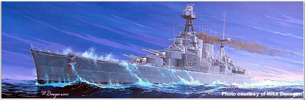
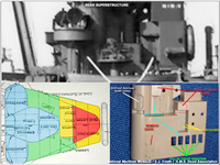
Box art for the Trumpeter kit
Background
There have been many commercially produced model kits of H.M.S. Hood over the years. The most popular variants appear to be those depicting the ship "as sunk" in battle with Bismarck on 24 May 1941. The Trumpeter 1/350 scale kit was the first of three "as sunk" Hood models released by Trumpeter. It was later followed by 1/700 and 1/200 scale kits.
Trumpeter's goal was to create the most accurate model kit of Hood to date. To that end, they consulted many reference documents and websites. They also sought out inputs from various experts on the ship. Among those consulted were members of our own website staff.
They asked us to review and comment upon the initial kit designs. To facilitate this, they provided me with a basic 1/350 scale "5 view" dot matrix print out of the ship consisting of plan (overhead), port & starboard profiles (side views) and fore & aft views (directly ahead and directly astern). Although the drawings were limited in scope and were a bit "fuzzy", I was able make many corrections and suggestions. Much of this information was based upon recent discoveries concerning Hood's final appearance (things not in any books or existing plans in print at that point in time).
The kit finally reached consumers in 2005 and at the time of writing, is still widely available. It retails for roughly £90 / $110 US. Actual price will of course vary. Please check with a local or online hobby retailer of your choice for latest prices and availability.
Moulding & Detail
The kit consists of 533 injection moulded pieces moulded in grey and red plastic (the lower hull is moulded in red). The kit contains 8 sprues, upper & lower hull, 4 deck pieces, waterline plate and display base. In addition to the plastic kit parts, Trumpeter also provides decals plus a few photoetch ladders, radar, spars and cables. An instruction manual and colour painting guidelines are also included. Note: Trumpeter also offers a separate 27 piece upgrade set for this model. It consists of machined 4" and 15" guns as well as propeller shafts and screws. Click here for more information.
Final Assessment
The model is not perfect; there is room for additional detailing and improvement, but will still be good enough for most people. The kit, as-is, builds into a reasonably accurate depiction of Hood with minimal difficulty straight from the box. Our overall assessment is that the kit is among the better mass-produced large scale styrene/plastic models of Hood as sunk and we highly recommend it.
The next portion of this article deals with the kit's various issues and offers recommendations for detailing and improvement. Those of you who want the most accurate model of Hood possible are encouraged to read on.
Corrections & Suggestions for Improvement
Before going any farther, I would just like to say that the purpose of this article is not to berate Trumpeter. We appreciate and are grateful for the fact that they produce models of Hood. They've helped make it possible to put miniature Hoods into far more homes than ever before. This is can only help in our efforts to ensure the ship, and more importantly, her crew, are remembered. The purpose of this article is simply to help modellers make better renditions of the ship should they wish to do so. Its up to each individual to decide how far they wish to go. Only do what you feel comfortable with.
Overview
The kit has a few errors, most of which are minor. There are, unfortunately, a few major errors as well. Simply put, I didn't catch some errors in the design phase as they were difficult to discern using the simple drawings provided. I would have required additional views from various angles and perspectives, but there were no such drawings available. Additionally, some detail issues arose due to production limitations (steps taken or not taken to keep the cost within reasonable limits). Lastly, and most significantly, there are a number of "new finds" or "re-discoveries" rather, that have been made in the years since the kit's design was finalised and went into production (even more things that aren't in any books or plans). Believe it or not, although Hood was quite famous, she was not as well documented (during wartime) as one might think! We still make new "discoveries" from time to time!
We'll cover the various issues starting with the painting instructions, then moving onto the kit's components.
Painting Instructions
Outdated Kit Painting Instructions - We've discovered actual color film footage as well as previously forgotten/overlooked official paint records/documentation since this kit was first released. As a result, much of the kit's color suggestions are incorrect.
- Best Painting Instructions - For the absolute latest and greatest on Hood's known paint schemes, please see our article on the Paint Schemes of H.M.S. Hood, 1920-1941
 Hull
Hull
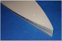
Hull Plating- The hull plating on the starboard and port sides of the bow and stern is a quite exaggerated; its much thicker and deeper than it should be at this scale. This is demonstrated in the photo to the right. This is a minor issue however, and the average modeller can ignore it. Those of you striving for total accuracy can alter the plates if so inclined. The depth of the plating can be reduced through scraping/sanding or by filling recesses with styrene. It could also be removed then reapplied with thin sheet styrene or built up with styrene, tape and primer/paint (i.e., Mr Surfacer 500). Regardless of the method, it can be difficult to get perfect edges and shapes. Click here to see a photo of the bow plates on the actual ship.
Lower Hull - The lower hull (for those of you building the full hull version) has a slight fit issue; its slightly shorter in length than the upper hull. Its easily fixed with plastic and putty. The lower hull is is also essentially smooth and lacking in plating detail. This is another relatively minor issue and something most modellers can ignore. Those wanting intricate details, however, may wish to add the plating (and various water intakes, etc). Sheet styrene, etching, primer/paint buildup, careful shading, etc., could all be ways of adding the detail. A recommended source for the plating detail is the "Hood - Expansion of Outer Bottom Plating" plan at the National Maritime Museum (Note: the original plan is in a fragile state and is currently undergoing repairs. Sadly, it is not currently available right now.).
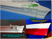 Hawse Pipes- There are four of these on the kit: one on the port bow, two on the starboard bow and one at the very end of the stern. . Trumpeter only moulded the raised lips/outer edges. We recommend opening-up at least the stern and rear starboard openings. This is because these two openings were not used in 1941. They were wide open and very visible. Those of you striving for ultimate accuracy could also consider opening the two forward-most openings as well...but as these will be blocked by anchors, it isn't really necessary. If you do decide to create the hawsepipe openings, remember to connect them to the corresponding openings in the deck(s) above.
- Suggested methods for recreating the hawsepipes- One method is to simply drill and file-out the openings. Its just a matter of drilling at the correct angle (imagine the drill bit is the anchor itself; you want to ensure the deck and hull openings are aligned). From there, the opening can be gradually enlarged angled and smoothed out. Putty or plastic stock/tubing can be applied to fill any unsightly gaps. Another method is to build up the area inside the hull/under the deck with plastic stock, sprue goo or plastic modelling putty first, and THEN drill out/repeat the above steps. If you do opt to use traditional putty or sprue goo, build it up carefully as these run the risk of softening and possibly distorting the kit's plastic! Important - Those of you using photoetch should note that when it comes time to work on the focsle deck hawsepipe openings, only the unused aft starboard anchor deck hawsepipe openings was covered with a grating. The other two deck openings were uncovered.
Hull Portholes/Scuttles- The hull porthole/scuttle arrangement for Hood varied slightly from port to starboard. Port and starboard were not mirror images of one another. They were close/similar, but there were some slight differences in numbers and positions here and there. As for the kit, the general placement of portholes/scuttles are close. Indeed, it is close enough for the average modeller. Those striving for additional accuracy will likely want to address the errors: There are several on the port side of the hull that are slightly out of position though. These are illustrated on the following two images, both courtesy of Maarten Schönfeld of Belgium: Port Bow & Port Stern. Note: the white spots are the filled-in portholes and arrows indicate the corrected locations. There is one error on the starboard side as well- there is a single porthole below the bitts and abreast the capstans that needs to be filled-in with putty.
 Degaussing Cable/Coil- The location/course of the cable is mostly correct, but the appearance of the cable itself is wrong. The actual ship had a combination of single and dual cables: There were dual cables (one mounted above the other) fitted around her bow. The top one was slightly thinner than the lower one. These extended rearward until roughly abreast "B" turret. At this point, they connected to a single cable. This single cable ran aft outside the enclosed focsle deck until reaching the point somewhere aft of the quarterdeck break. The exact point is currently unclear, but it would appear to be abreast "X" turret. From here, two cables were used to encircle the stern.
The cable(s) and fasteners were fitted to the hull as uniformly as possible. Despite this, there were areas along the bow and stern where the dual cables took on a sloppier/more irregular appearance. The fasteners also became misaligned. It has always been assumed that the port and starboard side configurations were similar with the exception of the portion that passed above the anchors ...there would have been a larger segment of cable to starboard as there were two hawsepipes to pass over. There is however, some question as to the exact layout of the cable at the quarterdeck break- recent photo and film analysis seems to indicate that the cable did indeed dip down significantly on the port side of the quarterdeck. The opposite is true of the starboard side- photographic analysis indicates that the cable did not dip down on the starboard side.
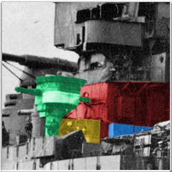
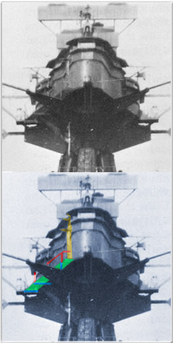
Regarding the portions that passed over the anchors, the Trumpeter kit has wrongly shaped cable fairings. These are the raised panels above the anchor hawsepipes. Photo analysis has shown that both sides were "stepped" in appearance. See the image to the right for the specific shape. The railings are in green, the degaussing cable in blue and the stepped fairings are in red. This is a very easy fix- simply file a step-down into each fairing.
Overall, I suggest that modellers carefully remove the moulded on degaussing cable and replace it with an aftermarket brass photoetch cable or strip styrene. Its easy to gouge the hull or damage other detail, so go slow when removing the cable!
Decks
 Forecastle- This part (referred to in the kit instructions as the "Fore deck") needs some minor detail alterations/augmentation. As mentioned earlier, the hawse pipe openings need to be drilled-out and connected to the hull side hawse pipes (see "Hawse Pipes" segment above). Also, scrape and sand off the moulded on anchor cable/chain. Aftermarket chain or built up photoetch would be more appropriate for this scale. If you are so inclined, you can also replace the various hatches with aftermarket photoetch hatches (to include adding missing hatches...such as the one behind "B" turret). They simply look more realistic at this scale. This applies to the other main decks as well. I have been told by Gary Dunstan of Australia that the anchor capstans (parts F45 and F46) appear to have been moulded upside down. He suggests clipping off the mounting pins and then attaching the parts upside down. Please be aware that there is a minor fitting issue with the focsle and central deck piece (one appears to be thicker then the other. It will be necessary to reduce the underside of the focsle piece a wee bit. he various winches are all too small and too flat. Suggest building these up with styrene and brass, or, buying aftermarket parts where available.
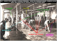
Enclosed Focsle Deck/Waist/Side Batteries - These are the long somewhat open areas along the ship's side between the hull and the Shelter Deck. These were the former locations of Hood's 5.5" batteries (which were removed before 1941). This area can be detailed by adding hatches, ladderways, vents., doors and windows were applicable. Additional detail can be added by including the numerous support pillars which helped support the deck overhead (many of which were positioned under the boat crutches). There were also ready-use ammunition boxes, Denton rafts and other materials stored in the area.
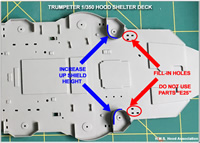 Shelter Deck- This part (referred to in the kit instructions as the "UP deck") is mostly accurate. It only needs some minor changes. First, there are three small holes just forward of each forward UP splinter shield/bulwark. These are there to allow you to mount parts E25 (Step 12 on Page 8). These items were not actually present on the real Hood. These holes can be filled-in and the boxes can be moved down to the enclosed focsle deck (you can see similar boxes/lockers in the above photo of the men scrubbing the deck).
Additionally, if so inclined, replace hatches with photoetch. There are some instances of moulded-on vents that need to be replaced or augmented. Two notable examples are the twin vents just forward of the rear/centre splinter shield/bulwark at the end of the deck. Trumpeter moulded these as small squares rather than rectangular hooded vents. I suggest replacing these with plastic strip stock. Also, Trumpeter forgot to include a ladder way - instead they moulded it as a large protrusion (they mistook its canvas cover as a structural feature). Cut this out and square the edges. Refer to the nearby ladder ways for the correct shape and size.
 Quarterdeck- (Rear deck). Replace the hatch just aft of "Y" barbette with photoetch. Add the missing hatch between the rear screens and "X" turret. Also, be sure to drill out the rear hawse pipe. There are also some fairleads missing from this area. Please consult plans to determine size and placement. The various winches are all too small and too flat. Suggest building these up with styrene and brass, or, buying aftermarket parts where available.
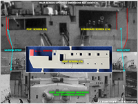
Rear Screens - These are the large vertical areas below the rear of the Boat Deck and at the front of the quarterdeck (parts C9 and C14) These correspond to the end of the superstructure outside of the Admiral's and Captain's suites (where Hood wore her name plates). Trumpeter molded these as mirror images of one another, but in reality they differed slightly: the rectangular opening in the portside screen was wider than the one to starboard. This can be easily fixed by trimming inside the forward edge of the rectangular opening in part C9. The positions of the portholes in both screens are close but some appear to be slightly off. This can easily be remedied with a set of plans and a drill though. The lower slotted vents in those screens were both covered by square shield by 1941.
Armament/Guns
 15" Main Gun Houses/Turrets- The four large gun houses (parts E5 and E7) are the most serious problem with this kit. For reasons unknown to us, Trumpeter modelled these with ridges running around the edges of the roof plates. The ridges correspond to the bolts that held the roof plates in place. The result is that the roof panels look recessed. There was no such ridge on the actual ship...just the bolts. In addition to this, the turrets are also shaped a bit too angular. They lack the square view ports in the front and the small ledge between the barrels. Some of these problems are difficult to fix. One would have to fill in the roof recesses and try not to remove the roof bolts. Alternatively, one could also sand off the bolts and ridges and then reapply the dozens of tiny bolts (using something like the railroad rivet set by Archer). It would be tedious and difficult, but it can be done. The best fix would be to replace the kit gun houses with aftermarket 3D printed or resin turrets (of which there are some splendid examples available!). You might as well use brass/metal barrels while you're at it.
- "B" Barbette Vents- "B" barbette (the base upon which the actual gunhouse sat) is at the very front of the "Center Deck" part. There is a minor issue with some of the "vents" which surround (are molded into) the barbette. First, there are too many (there were only two in the front), and second, some should be wider and/or taller than others (especially around the back). It should be a simple matter to cut/file off the erroneous vents and replace them with correctly sized plastic stock.
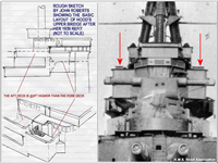
- "X" Gun House Platforms- Replace these (parts C11 and C12). Do not use any of the current photoetch products as none (to the best of my knowledge) are quite correct. You can use the support brackets, but discard the actual platforms. These were not flat angular platforms in 1941. They were actually two identically sized frameworks (when viewed from above, they were made up of square segments with X cross beams in the centre of each square). Each "platform" consisted of three such squares. The only reason one appears smaller than the other is because of the changing shape of the turret beneath them. This causes a bit of an optical illusion. Click here to see an image of the frameworks (on EJ Foeth's model). For those who still aren't convinced, here are two photos. Still not convinced? Then here is yet another photo.
The latest photo to show the frameworks in place was taken in Spring 1941. Please note that the framework below the director was slightly trimmed by the Spring of 1941. In this last photo to the right, you can see that it no longer reaches the angled rear edge of the gunhouse. It appears to me that one segment of the framework was removed along with the large corner angular supports. Only a trace of their attachment points remain. With so much documentation, its difficult to believe that this error keeps getting repeated; Even most aftermarket photoetch producers have gotten this wrong!
- Vents on "B" and "X" Gun Houses- These gun houses each had a pair of slim vents that were attached to their rear bulkheads. These can be replicated with strip styrene.
- "Bridge" on "X" Gun House- In addition to the aforementioned platforms/frames, there was also a small "bridge"/platform permanently attached to the upper rear/centre of X gun house. This allowed access to/from the rear of the turret and the very end of the boat deck. This was in place for several years before the sinking.
- Additional Turret Info - If you're looking for additional detail information on Hood's turrets, please read the following article on this website: Takom's 1/72 Scale HMS Hood Mk 1 15"/42 Gun Turret B Basic Review Plus Suggestions for Correction & Improvement
Twin 4" Secondary Armament- These seven mounts (parts E11-E13) are largely correct in size and shape but lack detail. You can make these far more realistic by incorporating photoetch and metal barrels. Most of the surrounding splinter shielding is correct in general appearance. Only the shielding for the forward most guns needs work:
- Shields for 4" P1 and S1- The 4" shields were not level with the deck, but rose in the middle and at the very front.
 UP Rocket Launchers- The five UP launchers (parts E33 and E34) suffer from a lack of detail. The base (part E33) is also not entirely accurate (especially the port/left side). It should be altered to more closely reflect the correct shape of the base. It may also be possible to replace it entirely with an aftermarket resin part. The rocket cage (E34) should either be augmented or replaced with photoetch. Note that ALL FIVE splinter shields/bulwarks which surround the UPs need the to be reshaped. Detailed photo analysis has shown that the shields were shaped differently than previously thought.
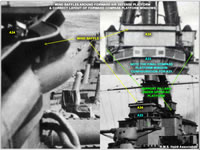
- "B" Turret UP- This mount sat inside a circular base. Detailed photo analysis (since the kit was released) has shown that the splinter shield/bulwark encircling the base was not uniform in height. It actually doubled in height for short spans directly to port and to starboard. Simply add sheet styrene to the applicable locations on part D15.
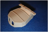
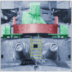
Also note that the UP platform itself is not a large rectangle supporting a circular centre piece. In reality, it consisted of two small outer platforms (supporting ready use lockers and a small working space) and the centre circular "tub" holding the UP launcher itself. The outer platforms were roughly half the depth of the central circular platform. There were supports below each edge of the small outer platforms as well as the edges of the circular platform. There was also an offset support in the front and at least one large angles strut in the rear (connecting the lower rear edge of the circular platform to the upper rear edge of the turret itself. In the photo to the right, the main UP platform, launcher and ammunition boxes are shown in green. The splinter shield/bulwark is red. Another view can be seen by clicking here.
- Forward Boat Deck UPs - The two forward shields need to be altered slightly. Two steps need to be added to the forward portion of the shield. To see the correct shape, please take a look at this photo from our Trumpeter's 1/200 kit review.
- Aft Boat Deck UPs - These are close. The raised/upper shields were not centred but slightly angled to the front. This can be fixed by carefully removing a small segment of the rear portion of the raised sections of shield. Make the height match the lowest edges.
Pom-pom Anti-Aircraft Guns- The three pom-poms (parts E14-E16) are actually pretty good for an injection moulded kit. They could be improved by adding additional detail. Augmenting or even replacing the mounts with photoetch would work quite well. They could also be potentially replaced with aftermarket resin parts (which could also be augmented with photoetch details).
0.5" Machine Guns- These four machine gun mounts (parts E5) are too bulky. Replace them with photoetch. Note that two guns had shields and two did not. They require more work than just this though- the location of each mount needs to be altered.
- Forward Guns- ("Pip" and "Squeak") are mounted on part A19 (Conning Tower Platform). These guns were not shielded. If you look slightly inboard to where each gun is mounted, you'll see that Trumpeter moulded four small "hatches" (2 per side). This is an error. This should actually be a single ammunition box. Remove the erroneous hatches and add one small box in their place. Also, the areas directly below each gun emplacement were open. The centreline area between the emplacements (directly below the narrow portion of the platform above) remained closed.
- Rear Guns- ("Paul" and "Simon") the guns sat atop pedestals (parts E3). These two guns did have shields. Cut off the circular plastic wall atop the pedestal, and ONE of the two small boxes. These "walls" were actually rails. You can replace them with photoetch.
As for the boxes, they held ammunition aboard the real ship. There was actually only one box mounted on each pedestal (a second box was mounted on the deck inboard of the pedestal).
Forward Superstructure/Bridge
Bridge Base/Lower Bridge- This is formed from various parts, most notably A2 and A3 which need to be extended at the rear (to match the rear edge of the part A1). More on this below. There are also a number of other important corrections and additions to be made to this area:
- Admirals Signal Platform- This is part A1. I suggest augmenting or replacing the signal flag lockers (the four rectangular features at the very rear of part A1- they are in blue in the photo below/right) with photoetch. There are also some important additions to be made to this area:
- Underside- The sides of the lower bridge were extended aft in 1940. This can easily be addressed with some sheet styrene .
- Side Splinter Shields/Bulwarks - As depicted on part A1, these outer raised sections are roughly correct but lack some of the actual variations of height of the real shields aboard Hood. The stanchions could be a bit thinner as well. This could easily be fixed by sanding off the existing raised stanchion details, adding the "dips" in the bulwark and then replacing the stanchions with thin round plastic stock, wire or photoetch. Of course, this is a minor issue and most folks could choose to leave it as-is.
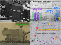
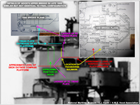
 Splinter-proof Shelters- In 1940, narrow enclosures were built on this deck- one to port and one to starboard. They were situated between the HACS Mk III* pedestals (parts E21) and the side of the bridge (parts A8/A9 and A10/A11- the rear parts of the Conning Tower Platform above this level. This area is shown in page 14 of the kit instructions). They are shown in yellow in the photo to the right. They were literally attached to the tube part of the HACS Mk III* mounts (green area in the photo to the right) and the lower sides of the Conning Tower Platform (red area in the photo to the right). These shelters were about the same width as the HACS Mk III* pedestal "tube". The shelters will go from the deck to just beneath the actual HACS (leave room for the HACS to rotate. There will be a small door in the shelter's rear very close to the HACS pedestal. Of course, before you can do this work, you will first need to modify a portion of the Conning Tower Platform (see below). Click here to see a schematic of the shelters.
- Signalmen's Shelters- These were located below the 0.5" MG mounts on the bridge (immediately behind the conning tower). This part is moulded as a solid area. Its necessary to drill, cut and file openings under the 0.5" MG. From there, plastic can be used to create missing decks and bulkheads where necessary.
- HACS Mk III* Directors- These are much nicer than those in any previous model, but are still a bit basic in shape. They could benefit from extra detail work such as under-hanging boxes, extended collar/flange around the upper rear, view ports on the front, etc. It should also be noted that the dome top covers were rarely ever used and not used at all by the time of Hood's loss. That being said, the top surface could benefit from detailing as well. Click here to view an official schematic of the director's exterior. Fortunately there are excellent 3D-printed replacement parts now available.
- Carley Floats (Rafts)- These are part(s) F14. We've discovered that Hood's Carley Floats were moved aft in early 1941. As a result, the positions indicated by Trumpeter are incorrect. There were actually only two total rafts mounted to the bridge. These were positioned (one to starboard and one to port) just forward of the wide/extended corners of part A1, roughly abreast the rectangular vents from the step 8 of the kit's instructions. This is a very noticeable change, but something very easily accomplished simply by filling the mounting holes and attaching the floats in the area indicated above.
Central Bridge Decks- This area is close in appearance, but could benefit from some corrective actions.
- Forward 0.5" Machine Gun Bases- The area under the 0.5" MG should be opened up/hollowed out . Please note that there was still a small square structure under the center though (between the forward edge of the Conning Tower Platform and the Conning Tower itself).
 Conning Tower
Platform- This is composed of various parts as indicated in step 10 of the kit instructions. In the lower right hand corner of the instructions, you can see the assembly of the Conning Tower Platform. You need to make modifications specifically to parts A8 and A10. Basically, remove the little square outcroppings on the lower/rear corner. In reality, the bulkheads were vertically flat, with nothing sticking out (other than voice pipes and of course, the Signalmen's Shelters mentioned above). There was also nothing sticking out to the rear at the bottom (most drawings/plans of this area are incorrect). There were, however, some liquid tanks mounted on the rear sides of the aft portion.
Conning Tower
Platform- This is composed of various parts as indicated in step 10 of the kit instructions. In the lower right hand corner of the instructions, you can see the assembly of the Conning Tower Platform. You need to make modifications specifically to parts A8 and A10. Basically, remove the little square outcroppings on the lower/rear corner. In reality, the bulkheads were vertically flat, with nothing sticking out (other than voice pipes and of course, the Signalmen's Shelters mentioned above). There was also nothing sticking out to the rear at the bottom (most drawings/plans of this area are incorrect). There were, however, some liquid tanks mounted on the rear sides of the aft portion.
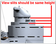
- Conning Tower- This is composed of parts A17, A19, A30, A28, A20 and A29. When assembled, the various view port slits are not the same height. One row in particular is too tall- the ones created by adding part A30 to part A19. There are also prominent gaps. It may be possible to reduce the slit heights using styrene strips. This, combined with careful gap filling should help make the structure more correct in appearance. Note: When finishing the Conning Tower, please take great care. I've noticed that most people do not attempt to address the seams...and this detracts from the overall quality of many finished models.
- Admiral's Bridge (A18)- The general overall outer shape of part A18 is more or less correct, but its missing a few details:
- Splinter Shield/Bulwark - The Admiral's Bridge was expanded in 1939 and a low splinter shield had been added to the angled front segment of the platform (which is correct on part A18). The rest of the platform's perimeter was ringed by railing (which was sometimes canvas-covered). All but the very rear-facing edges railing was replaced by a spinster shield/bulwark by early 1941. Please note that this new bulwark shield was slightly taller in height than the existing bulwark at the front of the platform.
- Remove Director "Knobs" - Remove the two small "knobs". These were gun control towers which were gone by 1940.
- Inboard Screen Detailing - As originally designed, the Admiral's Bridge platform was drafty and required an inboard set of screens. These screens are represented by part A21 and A22. We know that these screens were still aboard in 1940 and photographs seem to suggest (but not entirely confirm) that they were still in place in 1941 (even though the need for them would be questionable due to the new outer bulwarks). The tall portion of these screens appear to have consisted of windows/frames and may have connected to platform support pillars.
- Deck Opening- Also note that there was a small triangular opening in the deck towards the port/rear of the platform.
 Upper Bridge- These decks are close, but not quite accurate. A few minor modifications are necessary. Do not rely upon the Kagero 3D publication or World of Warships as both have the wrong ladder arrangements.
- Compass Platform and Torpedo Control Position- The Compass Platform is composed of part A23 and the Torpedo Control Position is the square it sits against in the centre of part A27. Take great care to fill-in gaps below the Compass Platform windows (one could also correct the configuration of the forward three windows if so inclined). It might also be beneficial to increase the overhang of the roof slightly. As for the Torpedo Control Position, the square structure is too narrow. It should be the same width as the Compass Platform. This section can be widened with styrene strips. This section is capped off with part A24. The rear portion of A24 (with windows) is of course too narrow. Modellers should cut this off and then in half and reposition the halves to align with the newly widened area of part A27. The centre gap can be filled with styrene. As for the rest of part A24, it will be covered in more detail later.
- Forebridge & Torpedo Control Platform- These structures are comprised of parts B3, A26 and A27 (step 12). The Forebridge (A26, B3 and the front half of B27) is the large blocky structure (and lower deck) at the front of the bridge outside the Compass Platform. The Torpedo Control Platform is the elevated deck behind this (the rear half of part B27). Trumpeter created an odd internal structure with the combination of B3 and A26. In realty, this area was open and the deck was at the same level as the Compass Platform entrance/exit doors. The main problem with A27 is that its shown has having one level. It actually stepped up in height (@3ft or so) abreast where the Compass Platform ended (and where the outer splinter shield/bulwark steps up). There are a few issues to mend here:
- Recreate the ladderways- The ladderways in A27 are in the wrong place. The simplest approach would be to fill these in, then cut the same shapes further forward (alongside the rear edges of the Compass Platform/just forward of the raised sections of splinter shields/bulwarks). This in turn will expose the area below the Compass Platform. So, you'll also need to recreate the sides/doors to the Compass Platform. For a more accurate approach, do the same thing, but instead of cutting ladderway sized rectangles, cut out the whole forward half of the deck on A27 (but leave the rear half!). Remove the blocky sections of A26/B3 immediately below this. Using the interior edge of A27, trace and cut a new deck insert (and be sure to include a rectangular opening for the ladderway) from some sheet styrene. Glue these in place just below the doors of the Compass Platform.
- Add the Transverse Splinter Shield/Bulwark- There was a bulwark which should divide the front half of A27 from its rear half. This is easily accomplished with plastic stock, photoetch, etc.
- Add Photoetch Ladders/Steps - There should be ladders leading up to the Compass Platform and up to the Torpedo Control Platform (two to starboard, two to port).
- Air Defence Platforms- Hood had two open Air Defence Platforms (ADP) atop her bridge. The forward one (part A24) was situated directly above the Compass Platform, and the upper/rear one (part A25) was atop the Torpedo Control Position (TCP} between/around the tripod mast legs).
- Forward ADP Issues - The forward ADP is a bit plain and is missing its outer wind baffles (these surrounded the upper edge of the bulwarks). These can be added with styrene stock or possibly photoetch. The interior is also plain in that it lacks the various pieces of ADP equipment and the central switchboard. These can likely be added using aftermarket parts and styrene.
- Upper/Rear ADP Issues - Trumpeter has moulded this piece (part A25) too large and with a slightly incorrect splinter shield/bulwark arrangement. First, the front portion of this feature was not enclosed, but was open in the centre. Second the piece is too deep (front-back) and should be trimmed by @2mm. The benefit is twofold: not only do you correct the dimensions, but you also remove the incorrect forward splinter shield/bulwark. It can be replaced by two small segments to port and starboard, leaving the entire centre open. Remember that these pieced were straight at the outboard front section and then curled inboard. We also recommend adding support pillars beneath the outer edges of part A25.
 Widen the Torpedo Control Room Windows & Raise the Roof - Be sure to cut A24 to separate the windows of the Torpedo Control room from the actual ADP. Cut the window portion in half and ensure the outer edges align with the area below (remember, this structure was the same width as the Compass Platform). Fill in the gap with styrene and/or putty. Additionally, this area is a bit too low. It needs to be elevated by @1-1.5mm so that its overall height is @ 2.75mm higher than the deck of the forward ADP. You can take care of this by simply adding styrene strip to the exposed front section of the Torpedo Control Platform roof after you reduce the depth of the upper ADP (part A25).
 - Access to the Area Between the AD Platforms - There was a "gap" between the rear edge of the forward ADP and the and the forward edge of the Torpedo Control deckhouse/upper ADP. Simply trim off a little of the raised bulwarks of the forward ADP (part A24). There was likely a small ladder in the area allowing crew to access the upper platform (it was a significant step up of at least 3 ft). Outboard of this gap were angular platforms with railings around the front and sides and a ladder at the rear. This ladder connected down to the Torpedo Control Platform deck. The arrangements to port and starboard were identical. Note: We see many people choosing to use the Kagero 3D book as a guide in this area. The problem is, the Kagero 3D book has this area completely WRONG!
Other Bridge Recommendations- The bridge area is quite prominent and careful attention to detail should be paid. That being said, it might be worth the effort to put in some additional detailing such as the aforementioned underside support pillars for the rear Air Defence Platform (wire or tube styrene), voice pipes (using tube styrene), plus various instruments using plastic stock and photoetch.The addition of the 6 pedestal mounted binoculars to the forward Air Defence Platform and 2 such mounts to the rear Air Defence Platform would be a particularly nice touch. Replace all ladders with photoetch as well. Be sure to add the port and starboard lights to the forward edges of the rounded side protrusions at the outer edges of the Forebridge (A26).
 Spotting Top/Starfish/Foremast- This is generally accurate. The only major exception are the shapes of the small side platforms (these were rectangular, not rounded) and the rear "corners" of the starfish deck platform. In reality, these were very rounded in shape (click here to see a rough diagram). This feature is shown in period photos of the ship as well as images of the wreck. The upper rear legs of the tripod mast (part B5) could use some additional detailing for the cable trunking. This could be accomplished with sheet styrene. The starfish platform (part B6) under the spotting top is a bit thick but will be sufficient for most modellers. It is missing a support brace between the rear arms (see the wreck image above). I are as yet unclear if this brace was horizontal or was actually the remnants of the former upper foremast base. Those wishing for high detail can always replace the kit's forward starfish with aftermarket photoetch. Of course, bear in mind that no after market photoetch is currently 100% correct with regard to the shape or the spotting top starfish platform. It will need to be augmented. There are some other key changes and additions here:
- Spotting Top Windows- This is part B8. The windows are a bit too small and are not squared enough. Additionally, the top of this piece (the Spotting Top roof) is too flat in the forward area. It was slightly arched. The forward roof also does not overhang the windows as it should. In short, its a bit too basic and this is a notable problem. Suggest altering the windows and roof overhang with sheet styrene and photoetch (photoetch could possibly be used for the windows). with aftermarket photoetch or styrene. These windows are not square or quite large enough. Additionally, the top of this piece is too flat. It also does not have the roof overhanging the windows.
- Radar Hood- This is a new discovery. This is made up of parts D34 and D36. Remove the small "box" from the left rear of part D34. Fill-in the hole that remains. The port corner should be a mirror image of the starboard corner. There was no box here; for years, plans had been based upon partial photos and an optical illusion. In reality, the roof was raised slightly in the left rear corner. With the exception of this instance of a raised roof, the overall dimensions of the hood remained the same as always. This can be seen in the rough schematic to the right. The area in red (and yellow) is the raised section of roof.
I also suggest replacing the radar elements with aftermarket photoetch. Be careful though- most photoetch depicts the Type 284 radar as "flat". In reality the Type 284 had a central antenna which was open at the front (with numerous vertical bars and covered by canvas) and more or less curved at the rear. This was attached to a framework at the sides (with hexagonal panels) and from behind (by bars). This framework was connected at the rear to vertical supports which were attached to the rotating hood below. Click here to see a photo of Type 284s aboard ships.
 Add a Platform to Hood's Foremast Starfish- There was a platform fitted on the starboard side of the starfish, along the side of the Spotting Top, between the starboard/forward arm and the small signal light platform just aft of starboard/centre. This was spotted in dockyard photos from Spring 1941. The platform is narrow and has supports beneath it as well as a railing on top. At the forward end of the platform is a ladder rising up the side of the spotting top. Cut a notch in the overhanging roof here. In the top photo to the right, you can see the Spotting Top and starfish platform. Below this, you can see an annotated photo showing the location of the new platform (green), its underside supports (blue), its railing (red) and the ladder up the side of the Spotting Top (yellow).
Amidships/Aft Structures
Funnels- Largely correct, but suggest hollowing out caps (parts F8) and replacing the funnel grilles with photoetch. Two minor details that can be added near the second funnel are the coppersmith and blacksmith's shop exhaust funnels. These are easily added using plastic tubing or wire. The base for the rear funnel is incorrectly shaped- it was not angled as seen in several drawings as well as this kit. It was actually the same shape as the one used for the fore funnel. The only difference is that a small segment at the very front and very rear was cut away (to help it fit atop the large vent). Other things to consider are reducing the depth of the rings which run around the funnels (they were much flatter on the actual ship) and perhaps adding simulated rivets.
MFDF structure winches - The various winches are all too small and too flat. Suggest building these up with styrene and brass, or, buying aftermarket parts where available. Only put photoetch railing on forward and rear edges (no railing to the side).
Tubes near forward pom-pom guns- (parts E32, see page 14 of the kit instructions). Cut off the straight tube portion of each. Also be sure each has a flat top (round when viewed from above).
UP and Gun splinter shields/bulwarks - All UP splinter shields/bulwarks as well as the forward-most 4" gun emplacement splinter shields/bulwarks need to be reshaped to match the actual ship
Forward two UPs - These were more stepped in appearance. To see the correct shape, please take a look at this photo from our Trumpeter's 1/200 kit review.
Aft two UPs - These are close. The raised/upper shields were not centred but slightly angled to the front. This can be fixed by carefully removing a small section to the rear.
 4" Shields for P1 and S1- The 4" shields were not level with the deck, but rose in the middle and at the very front.
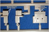
Motorboat Workshop- This is just behind the second funnel. The square features atop B28 are windows. Trumpeter mistakenly put grilles/mesh over these. They were NOT mesh covered, but had canvas curtains hanging inside (I sent Trumpeter a schematic of this structure). Also, be sure to remove the door and ladder from part B26. The only (currently) known door and ladder were on the opposite side. Please be aware that some of the aftermarket photoetch producers instruct modellers to place photoetch mesh over these windows...this is not correct! Again, they were curtained windows.
Engine Vents- The square engine room vent (parts B39, B40 and B47) located between the main mast and the After Superstructure is not shaped correctly. This vent no longer had an overhanging roof. It looked more like the vent just behind the After Superstructure. Additionally, all of these vents could use mesh detail from an aftermarket photoetch set. Click here to see an image showing this vent on the real ship.
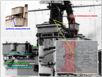
 Mainmast- The mainmast starfish is shaped incorrectly. I suggest replacing starfish platform (part D7), main derrick pulleys (the bumps on part D6) and tackle plus the Type 279M radar assembly (the two small items near the top of part D5) with aftermarket photoetch. Add the diesel exhaust pipe up the port rear tripod leg using wire or tube styrene. A rough schematic showing the correct layout of the mainmast starfish is shown to the right.
There was a small platform at the rear base of the mainmast centre tripod leg. This had controls for the main derrick. The area below the platform was partially enclosed (there was a bulkhead to port and one to starboard but the back was open). Trumpeter moulded it as a solid block with no detail. We suggest removing the block (but keeping the platform) and then adding small pieces of plastic to the sides.
 After Superstructure- The main portion of this is formed by parts D11-16 (step 16). For the most part, the overall shape/configuration is generally accurate. Certain small details need to be addressed:
- Top Deck- The splinter shield/bulwark between the two upper level searchlight platforms (on the side that faces the mainmast) on part D16 is too low. This should be raised slightly in height using plastic stock.
- Square Windows- Fill in or cover the square windows around the lower rear of the structure (sheet styrene). Photos suggest that although these were originally canvas covered, they were eventually plated over with steel.
- Portside Alcove- There is also a slight problem on the port side where the structure is indented (D11). There is a sharp edge at the top of the indent...this corner should be cut away. In reality this area was open (it should match the width and depth of the area below it. The area above it is correct. There may have been a small ledge or shelf in the area (difficult to tell from photos).
- Searchlight Platforms- We also suggest drilling out the doorways to the side searchlight platforms on parts D11 and D12. These doorways are right above where parts D17 and D18 attached.
- Additional Details- Add cruciform supports to the HACS Mk III* director pedestal (part E20) atop the structure. Also suggest detailing the HACS Mk III* (see earlier comments on this). Lastly, there is some external detail missing (i.e., slight "bulges" below the lower searchlight platforms, cabling, etc. This can be added with plastic stock. There are some misplaced and missing doors and ladders as well.
 Pom-Pom Bandstand- The bandstand (part B46) for the aft pom-pom (aka "Auntie") has two hatches mistakenly moulded
into it. Remove them and replace them with boxes. Additionally, the support/base of the bandstand (parts B31 and B32) is shaped completely wrongly. It was not rounded, but was actually angular (see photo to the right). This can probably be remedied with sheet styrene. There were also at least two canvas walls or splinter shields/bulwarks enclosing the forward and port sides beneath the bandstand as well. One was under the forward "flat" end and one was under the port side of the bandstand. Both shields extended from the deck to the bottom of the bandstand.
Hatches, Skylights & Vents - A number of these are slightly off in shape and/or location. We have not compiled a listing though- we must let you, the modeller, do some research! No worries, we've included some excellent recommended sources later in this article.
Boats
The boats are all somewhat under-detailed, but this is not surprising as Trumpeter (as well as us) had little to no reference material in this area. It may be possible to augment some boats with photoetch, or replace them with aftermarket parts. I highly recommend consulting Evert-Jan Foeth's excellent website On the Slipway for boat (and many other) details.
We recommend looking into some of the excellent aftermarket 3D printed boat sets. Of course, some even simpler shortcuts can be taken as well: Hood's small motor boats, Admirals Barge and open row boats were usually canvas covered. This will help you reduce the amount of time spent on detailing the kit.
Resources & References (Which Ones to Use & Which Ones to Avoid)
When building a detailed model of Hood, a thorough modeller should of course compile various reference materials. Of course, unless they are already familiar with Hood, they may not know which references can be trusted and which cannot. To aid in this effort, here are things you can trust (plus a few you shouldn't):
Good References (Recommended)
The following items are HIGHLY recommended as use for references when building models of Hood:
- HMS Hood Association website - This is our website. We have many photos and detailed historical information for Hood and crew.
- On the Slipway website - Our good friend Evert-Jan Foeth's impressively detailed site devoted to his work at creating the most accurate model of Hood possible.
- "Anatomy of the Ship - The Battlecruiser Hood" book by John Roberts - Excellent source of detailed drawings. Please note however, that the 1941 plan view of Hood is not entirely accurate. This only because at the time the book was originally created, certain features of Hood were not known or confirmed.
- "Hood Design & Construction" (AKA "Man o' War 6") book by Maurice Northcott - Excellent source of photos and detailed drawings. Please note however, that the 1941 plan view of Hood is not entirely accurate. This only because at the time the book was originally created, certain features of Hood were not known or confirmed.
- "The Battlecruiser HMS Hood: An Illustrated Biography 1916-1941"and "The End of Glory: War & Peace in HMS Hood, 1916-1941" by Bruce Taylor - Excellent sources of historical information for Hood.
- Warship Pictorial 20 - HMS Hood by Steve Wiper/Classic Warships - This has many excellent photos. .
- "Profile Warship 19" book by R.G. Robertson - Excellent source of photos, but do not rely upon the colour drawing as it is out of date and coloured incorrectly.
- David's Ships Youtube Channel- David has built an exceptionally well detailed version of the Trumpeter 1/350 Hood using this guide as one of his primary sources. His work has helped us identify various things we overlooked. He has an excellent video series outlining his work.
References to Avoid (Not Recommended)
The following items are widely available and seem to have found their way into many Hood enthusiasts bookshelves. At first glance, or to those less familiar with the ship, they seem excellent...and parts of them are. Unfortunately, they also have some very serious errors. The bad outweighs the good. We strongly advise against relying upon them as primary references when building models of Hood. If you do decide to use them, please be sure to balance the information by using other sources. You can also ask us questions or post questions on key modelling website forums:
- Profile Morskie 63: H.M.S. Hood" monograph by Jerzy Moscinski & Slawomir Brzezinski " - The plans associated with this book are quite detailed and accurate in a some areas, but there are also numerous substantial errors. Some were not known at the time the book was created but some were quite well documented. There are other errors that make no sense at all : the authors depict Hood as having two differently sized funnels!!! How on earth did they make such a major mistake? So the book in its current form should not be used as a primary reference source. Should they ever wish to correct the errors, we will be more than happy to help.
- "The Battlecruiser HMS Hood" by Stefan Draminski - There are two Kagero titles on Hood - one is part of the "Super Drawings in 3D" series, the other is part of the "Topdrawings" series. Both appear to come from the same source materials. On one hand, both contain extremely nice/well executed drawings and renderings of Hood. On the other hand, they also repeat many of the same mistakes made by Profile Morskie 63 (it may have been a key reference for this work). The major funnel size mistake was also repeated!!! This one is frustrating - it really is a well-made publication and could be very useful to modellers, unfortunately, too much is incorrect at this point in time. So, we cannot recommend it as a stand-alone resource. Important Note- We've contacted the author and he's a very nice gentleman. We've provided him with new information to help correct the drawings should the titles come up for new editions. We will be happy to help him get the right information. Until then, we must warn modellers about its accuracy.
Other Suggestions
Here are some other general detailing suggestions:
- Replace all ladders (inclined and vertical), cable/hose reels, wiring, etc, with photoetch.
- Add voice tubes with thin wire or strip stock
- Add electrical cable trunking, foot holds/hand holds around key superstructure items, metal plating, rigols over portholes/scuttles, etc.
- Replace mast yards, flag staffs, etc., with photoetch, wire or strip stock
- Update various mushroom and hooded vents with plastic stock or photoetch
- Add photoetch to all the ready use ammunition lockers (most of these boxes appear to have sinkholes/injector marks in their rears...be sure to fill these.
- Don't over weather the ship when painting it. Again, please see our article on the Paint Schemes of H.M.S. Hood, 1920-1941
Photos of Completed Kit
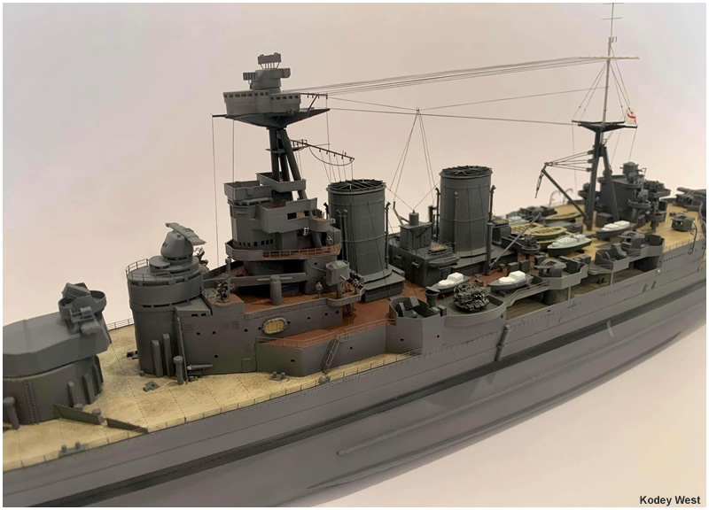
Shown here are various examples of completed Trumpeter 1/350 Hoods. Additional photos of other examples can be seen in our Models Gallery.
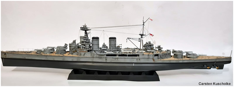
Above & Below- Two examples of super-detailed Trumpeter 1/350 scale Hoods. The top one was built by Carsten Kuscholke and the bottom one by Kodey West.
These show that excellent results can be achieved with this kit through additional detailing work.
Kit Build
You can read an article detailing the construction of this kit by clicking here.
Aftermarket Parts
A number of photoetch manufacturers have created parts for this kit. I have put together an alphabetically sorted cursory list below. This list is by no means complete, so if you know of something I have omitted, please be sure to let us know.
Big Blue Boy Model
This company makes a super-detail set for Hood. They also sell various other components (metal gun barrels, pom-poms, etc. I have not seen the set in person yet, so are unable to verify its accuracy. Based on the photos we've seen online however, it seems to be on par with other similar offerings. Note from website staff: If you have used this set and would like to comment on it (or send us some detailed photos) please contact usEduard
1/350 HMS Hood (53020) photoetch set: This set contains 4 sheets of photoetch details which include assorted railing, ladders, gun mounts, starfish platforms, vent grilles, boat parts, gun parts, radar, hatches, doors, bulkheads, splinter shield/bulwark supports and so forth. Very similar in content to other key 1/350 photo etch sets. Note from website staff: This set has too much railing (railing in wrong locations), vents where there shouldn't be any, and an incorrectly shaped foremast starfish (missing circular rear corners).Flyhawk Model
1/350 HMS Hood detail set FH350098: This set contains brass photoetch sheets and resin replacement parts for the Trumpeter 1/350 scale model of Hood. I have not seen the set in person yet, so are unable to verify its accuracy. Based on the photos we've seen online however, it seems to be of excellent quality and on par with or superior to other similar offerings.Gold Medal Models
1/350 Trumpeter Hood (350-57) photoetch set: custom fitted and pre-shaped main deck railing with pre-positioned cutouts for chocks, diagonal braces, & turnbuckle detailing; pre-sized specialized railing in all the correct styles for upper decks with diagonal braces, turnbuckle detailing, & simulated canvas covering where necessary; extra lengths of matching 2-bar & 3-bar railing for custom work; correct size vertical ladders; watertight doors in the correct sizes and in two styles including open and closed versions; inclined ladders in all required sizes with detailed foot plates; specialized inclined ladders with platform braces for Admiral's Cabin; detailed Admiral's Cabin window covers; "HOOD" nameplate letters with alignment jig; highly accurate Type 279 and Type 284 radar antennas; boat crane rigging and hooks in choice of stowed and working positions; small crane rigging; details for 2 pdr Pom-Pom guns including elevation rings, gun sights, ammo box covers, & pre-shaped guardrails; detailed side panels for 4" .45 cal. guns & .50 cal. machine gun mounts; pre-shaped see-through screens for all intake uptakes; paddles plus see-through bottoms for life rafts; highly detailed replacement yardarms in the correct shapes for both masts; funnel cap grilles for both funnels; rudders, oars, & 3-D relief-etched fold-to-shape crutches (chocks) for all ship's boats; detail for davits, griping spars, & jumping nets for two sea boats; detailed awning stanchions in bipod and tripod styles with matching drilling jigs for both; fold-to-shape cable reels in three sizes; anchor chain capstan brake wheels; replacement aerial spreaders; two leadsman's platforms; ladder well railings; two quarterdeck hatches with fold-to-shape canvas cover frames; four accommodation ladders with detailed davits, rigging, and foot plates with the name "HOOD" embossed in surface; three anchor hawsepipe cover screens; highly accurate replacement degaussing cable with correct shapes and clip arrangement including full-size drawings for modifying raised plastic hull plating above hawsepipes to the correct shape; pre-shaped Jacobs ladders for boat booms. Extra turnbuckles, eyebolts, & hand wheels are provided for custom work. A detailed 3-D relief-etched figure of VADM L. E. Holland is also included. Numerous spare parts are furnished in the event of loss or damage. Note from website staff: This is the only photoetch set to get the degaussing cable right. Its also the closest in overall dimensions to the actual ship. The only error is the Type 284 radar. To correct this part, you need to remove the vertical supports from the face of the upper radar antenna and attach them to the rear of said antenna. This set is highly recommended.1/350 Gold PLUS Hood Extra Details (350-37A): Augments main photoetch set (extra detailed parts for expert modellers). Contains Additional watertight doors in the correct sizes and in two styles including open and closed versions; additional fold-to-shape crutches (chocks) for all ship's boats; complete set of 3-D relief-etched skylight covers for U.P. deck; highly accurate replacement davits and griping spars for two sea boats in choice of stowed and deployed positions; 3-D relief-etched thwarts and internal stern gratings for ship's boats; additional detailed awning stanchions in bipod and tripod styles with matching drilling jigs for both; additional small handling davits in several styles; see-through window frames for fighting top; detailed fold-to-shape night life buoys with stowage racks; 3-D relief etched tampions for 15" gun barrels; boat boom brackets for hull sides; highly detailed aircraft catapult and launching shuttle for 1929 - 1932 Hood; struts and propellers for Fairey floatplane provided for scratch builders; highly detailed aircraft recovery crane with rigging and hooks for 1929 - 1932 Hood; X-turret aircraft platform sections; detailed jack staff with bull nose and ensign staff including braces & anchor lights; Extra eyebolts are provided for custom work. Numerous spare parts are furnished in the event of loss or damage. Note from website staff: This is a superb photoetch set and also includes accurate X turret frameworks! HIghly recommended.
Lion Roar
Click here to read our review of this detail set.Micro Master
Micro Master makes several 3D printed parts that will fit this model of Hood. To view his range of products, please visit Shapeways.Model Monkey
Model Monkey makes several 3D printed parts that will fit this kit. Simply visit Shapeways and search his site for 1:350 scale ship parts.Northstar Models
Northstar Models offers many interesting detail parts which may work with this kit.
Tom's Modelworks
1/350 Trumpeter Hood photoetch set: Designed specifically for Trumpeter's 1/350 scale Hood. Contains assorted railings; funnel cap grilles; degaussing cable; vertical and inclined ladders and accompanying platforms; boat crutches, boat interior parts, yardarms; pom-pom railings, Type 279 and Type 284 radar; boat davis; vent grilles; the ship's name and more.White Ensign Models
1/350 Hood photoetch set (#PE 3514): Designed specifically for Trumpeter's 1/350 scale Hood. Includes: Guard Rails, 0.5" Quad machine guns, 8 barrel Pom-Poms, Spotting Top starfish assembly, Anchors, Life buoy Racks, Mainmast rigging, Jack and Ensign Staffs, Main boat boom tackle, various davits, Semaphores, Various ladders, 284 and gunnery radar, Main director arm stays, Stern boarding pole, Searchlight lens cruciforms, Type 279 radar assembly, Spotting top yardarms, Funnel Cap grilles, Foredeck ladders, Wireless House Aerial Spreaders, Mainmast Starfish Assembly, Funnel Housing Vent grilles, Spotting top Station lights and Aerial Spreader, Degaussing Cables, Anchor Cables, Boarding Ladders, Vertical and Inclined Ladders doors hatches, tampions, Hood badge for display base and more. Note from website staff: The Type 284 radar is not correct. To correct this part, you need to remove the vertical supports from the face of the upper radar antenna and attach them to the rear of said antenna. Additionally, do not use the foremast starfish piece. The deck shape is quite incorrect (its missing the large round rear corners and several protrusions).Wooden Deck Veneers
Firms like Artwox, KA models and Pontos Model all sell wood decks for this kit. These are cut to fit over the kit's plastic decks (peel and stick). From what we've seen, all are about on the same level of accuracy/quality.
Other Reviews (Alphabetically Sorted)